
Integrated portable stand, power supply, and control panel

Active Publication Date: 2012-07-05
AIR SYST
View PDF31 Cites 22 Cited by
  • Summary
  • Abstract
  • Description
  • Claims
  • Application Information

AI Technical Summary

Benefits of technology

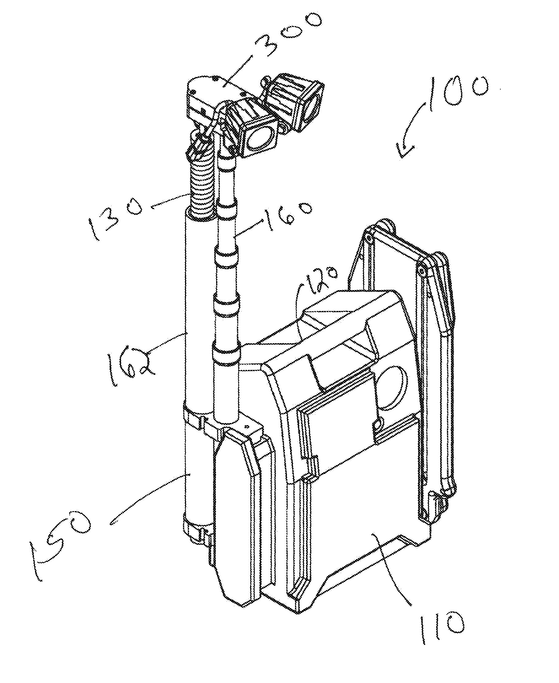
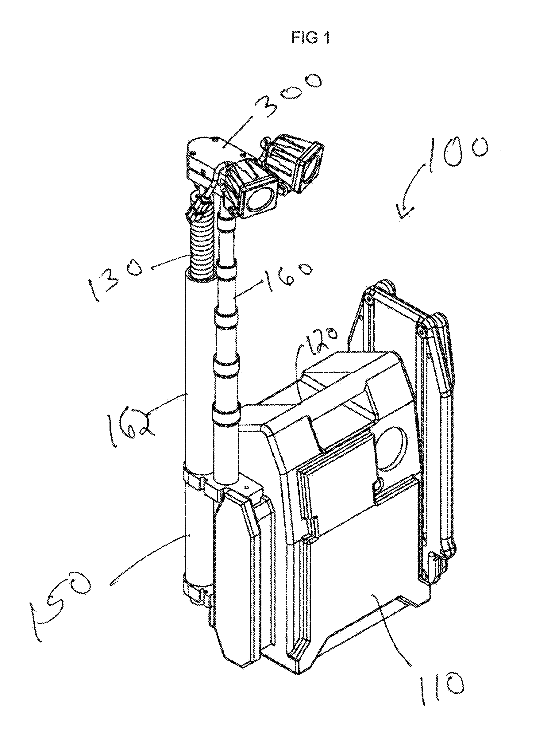
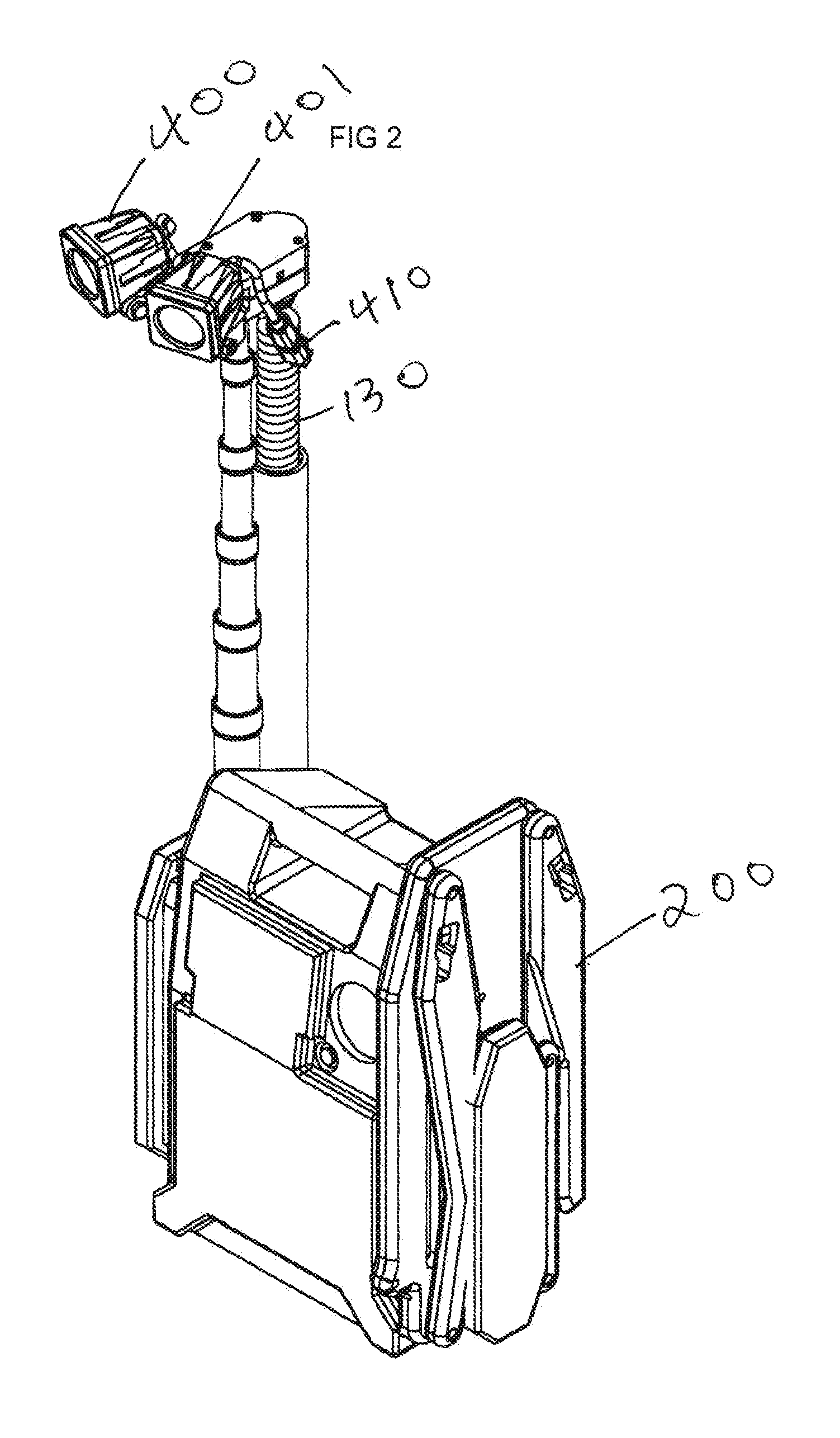
[0004]Referring to FIGS. 1 to 4, there is shown an exemplary stand of the present invention from different views. The stand of the present inventions comprises a main housing for holding a power supply and controller. A leg assembly is attached to the housing, shown in collapsed form in FIGS. 1 to 4, and shown in an extended configuration in FIG. 5. The legs of the leg assembly can be extended outward from the housing to increase stability of the stand. A telescoping mast is attached to the housing, and includes a mount for a functional device at the top thereof. Electric power and control signals can be transmitted from inside of the housing to the functional device by at least one cord that is coiled to reduce bulk. The power and control conduit is contained in a protective sleeve from which it can be extended when the telescoping arm is extended and into which the bias of the coil and gravity permit retraction into the sleeve when the telescoping art is retracted. Mounted on the top of the telescoping arm is a fitting for mounting a functional device, the functional device being show in the Figures being a light. The fitting includes a housing that enables electrical power and signals from the control conduit to be connected to the functional device, while also maintaining a weather tight seal. The fitting provides at least 2 directions of adjustment (also referred to as degrees of freedom), so that the functional device can be rotated about the axis of the telescoping arm and pointed up or down. Further details of exemplary embodiments of the present invention are provided below after a brief summary of the drawings.

Problems solved by technology

However, if there are multiple parts that need to be connected in the dark in order to set up the platform, work will be delayed, injuries can occur and parts can be lost and / or not available at all.
Even if there is a light, a stand that is not self contained and that requires connection of parts to erect for use causes a delay in starting work at the job site while parts are located, if not lost, and connected together.

Method used


Image

  • Integrated portable stand, power supply, and control panel
  • Integrated portable stand, power supply, and control panel
  • Integrated portable stand, power supply, and control panel

Examples


Embodiment Construction

[0012]The following provides further details of the present inventions as summarized above and illustrated in the drawings. Part numbers in the description correlated to one or more parts indicated in the drawings, but to focus attention on the features of the invention, not all parts are numbered or shown in detail. Referring to FIGS. 1 to 4, an exemplary, non-limiting embodiment of a stand 100 the present inventions is illustrated. A main housing 110 preferably contains a power supply and control panel. Access plugs for recharging and / or connecting the stand to a power supply are provided. In a preferred embodiment, a rechargeable battery is contained within the housing. In an embodiment, a 12 volt power port is provided on the main housing. The battery is preferably connected to a battery fitting to maintain it securely fixed in the housing and free from the environment. Preferably, the battery or other power supply is connected to electrical connections within the housing, and a...


PUM


Abstract

A portable stand with an integral power supply and controller, a mast for supporting a functional device and a stabilizing leg assembly comprises a main housing for a power supply, and connected to the main housing are retractable and extendable support legs and an extendable and retractable mast. The mast includes a mount for holding at least one functional device to form a single, integral unit that provides for storage, stable support and power for a functional device that is mounted onto the mast, and portability.

Description

FIELD OF THE INVENTION[0001]The present inventions relate to stands for supporting items in an elevated position with respect to the surroundings, and more specifically relates to stands that are portable, easy to set up for use at a site, easy to collapse for storage and transport, and that do not require connection of parts at a site of use to function nor disconnection of any parts after use in order to collapse the stand for storage and transport.BACKGROUND[0002]Reference is made to copending U.S. patent application Ser. No. 12 / 432,525, filed Apr. 29, 2009, entitled COLLAPSIBLE PORTABLE STAND WITH TELESCOPING SUPPORT AND INTEGRAL STORAGE CASE, which details relevant background regarding the ubiquitous need for temporary stands to support items, such as functional devices, at an elevated position with respect to their surroundings, and provides embodiments of solutions therefore. The disclosure of U.S. patent application Ser. No. 12 / 432,525 is incorporated herewith as if reproduc...

Claims


Application Information

Patent Timeline
IPC IPC(8): F16M11/04
CPCF16M11/28F16M11/10F16M11/2014F16M2200/08F21S9/02F21V17/007F21V21/00F21V21/06F21V21/22F21W2131/1005F21W2131/103
Inventor INTRAVATOLA, LAWRENCE SHANE
Owner AIR SYST
Learn More