
LED retrofit module for roadway fixture

a technology for retrofitting modules and roadway fixtures, which is applied in the manufacture of electric discharge tubes/lamps, lighting and heating apparatuses, lighting support devices, etc., and can solve problems such as thermal management problems in design

Inactive Publication Date: 2012-06-28
GE LIGHTING SOLUTIONS LLC
View PDF6 Cites 26 Cited by
  • Summary
  • Abstract
  • Description
  • Claims
  • Application Information

AI Technical Summary

Problems solved by technology

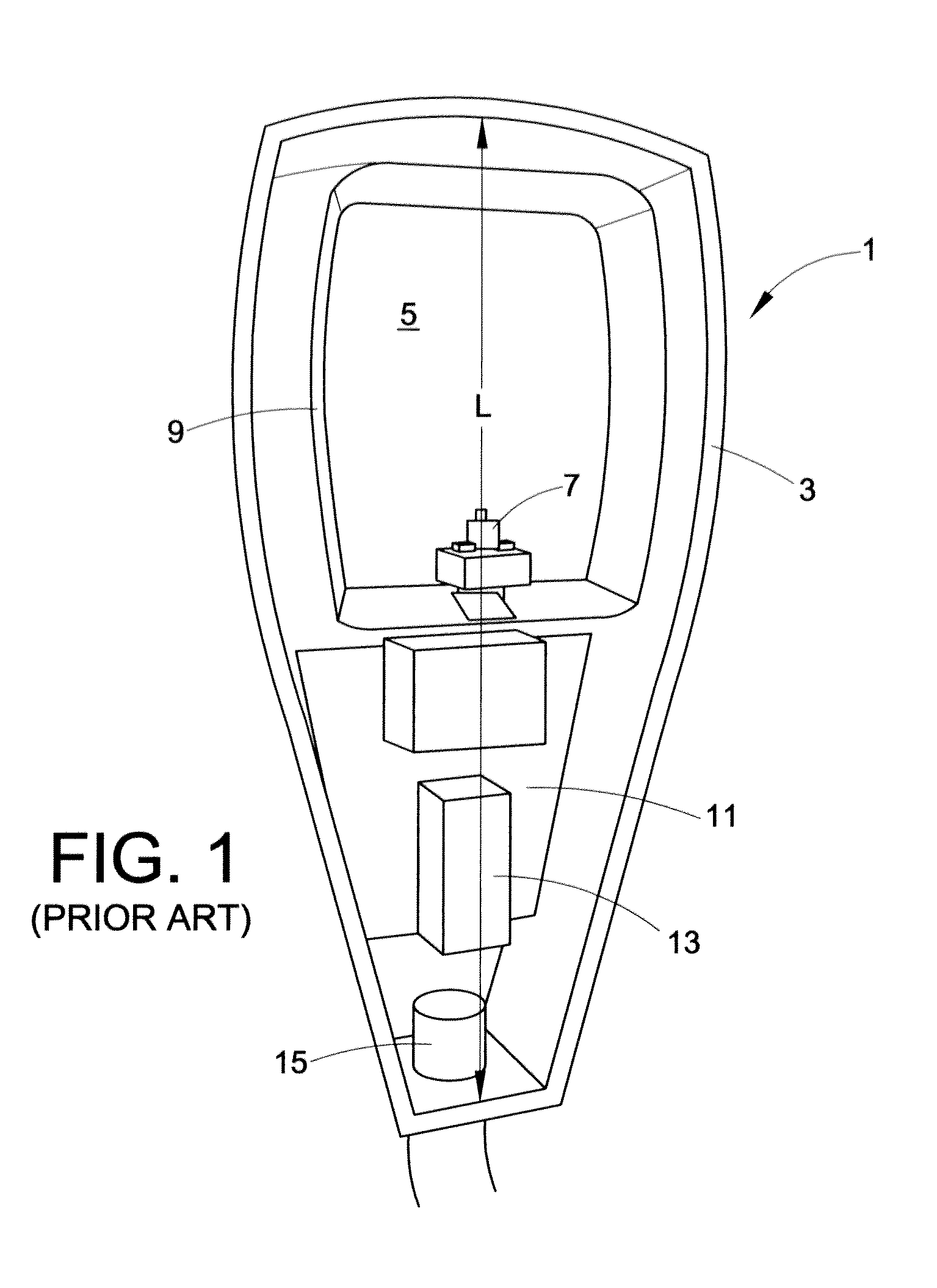
Although functional, this design can suffer from thermal management issues.

Method used


Image

  • LED retrofit module for roadway fixture
  • LED retrofit module for roadway fixture
  • LED retrofit module for roadway fixture

Examples


Embodiment Construction

[0017]The present disclosure provides a convenient and economical device for the replacement of an HID light source in a light fixture. The disclosure finds particular relevance to roadway fixtures, such as the commonly employed Cobra Head style. Of course, although reference is made herein to the Cobra Head style of fixtures, the LED lighting module described is amenable to other similar types of lighting fixtures.

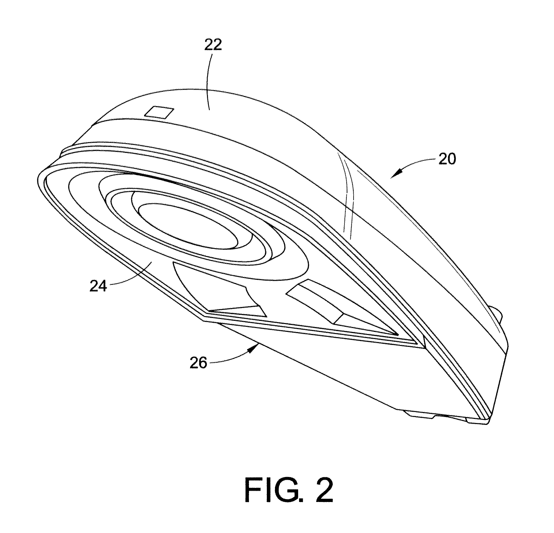
[0018]Referring to FIG. 2, a light fixture 20 including the subject replacement LED light source is depicted. More particularly, a standard roadway light fixture 20 including a main housing 22 has been modified to include an LED lighting module 24. In this regard, the perimeter of the LED lighting module 24 is shaped cooperatively to base opening 26 of the main housing 22.

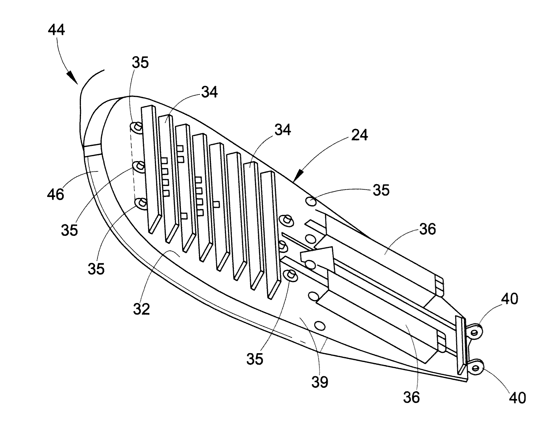
[0019]Referring now to FIGS. 3-7, the present disclosure provides a light engine module 24 including a plurality of LEDs 28 disposed on a printed circuit board 30. The LEDs can emit in combination at lea...


PUM


Abstract

A solid state replacement light module for a high intensity discharge light fixture. The module is comprised of an elongated generally planar body having a first side including a plurality of light emitting diodes and a second side including a plurality of heat dissipating fins. The second side further includes an electronic module. The body also includes a hinge mechanism suitable for attachment to the light fixture.

Description

BACKGROUND[0001]Exterior lighting is used to illuminate roadways, parking lots, yards, sidewalks, public meeting areas, signs, work sites, and buildings, to name a few examples. Traditionally, such lighting systems used high-intensity discharge (HID) lamps, often high pressure sodium (HPS) lamps. The move towards improved energy efficiency has brought to the forefront light emitting diode (LED) technology as an alternative to HID lighting in commercial and municipal applications. LED lighting has the potential to provide improved energy efficiency and improved light output in outdoor applications.[0002]The Cobra Head type light fixture is perhaps the most commonly found style of roadway fixture. It would be advantageous to convert existing Cobra Head style HID lamps to LED light sources without having to discard the entire fixture assembly. There is therefore a need for an improved LED retrofit solution for outdoor applications that does not require replacement of the existing fixtu...

Claims


Application Information

Patent Timeline
Patent Type & Authority Applications(United States)
IPC IPC(8): F21V11/00H01J9/50F21S4/00
CPCF21V23/003F21V29/004F21W2131/103F21V29/763F21W2131/107F21Y2101/02F21Y2105/001F21W2131/105F21Y2105/10F21Y2115/10F21V23/006F21V15/01
Inventor MRAKOVICH, MATTHEW STEVEN
Owner GE LIGHTING SOLUTIONS LLC
Learn More