
Programmable Camera and Video Reconstruction Method

a video reconstruction and camera technology, applied in the field of video cameras and video processing, can solve the problems of high-speed video cameras that are difficult to achieve, the fundamental limits of those methods, and the limited resolution of most conventional video cameras

Inactive Publication Date: 2012-06-28
MITSUBISHI ELECTRIC RES LAB INC
View PDF14 Cites 43 Cited by
  • Summary
  • Abstract
  • Description
  • Claims
  • Application Information

AI Technical Summary

Benefits of technology

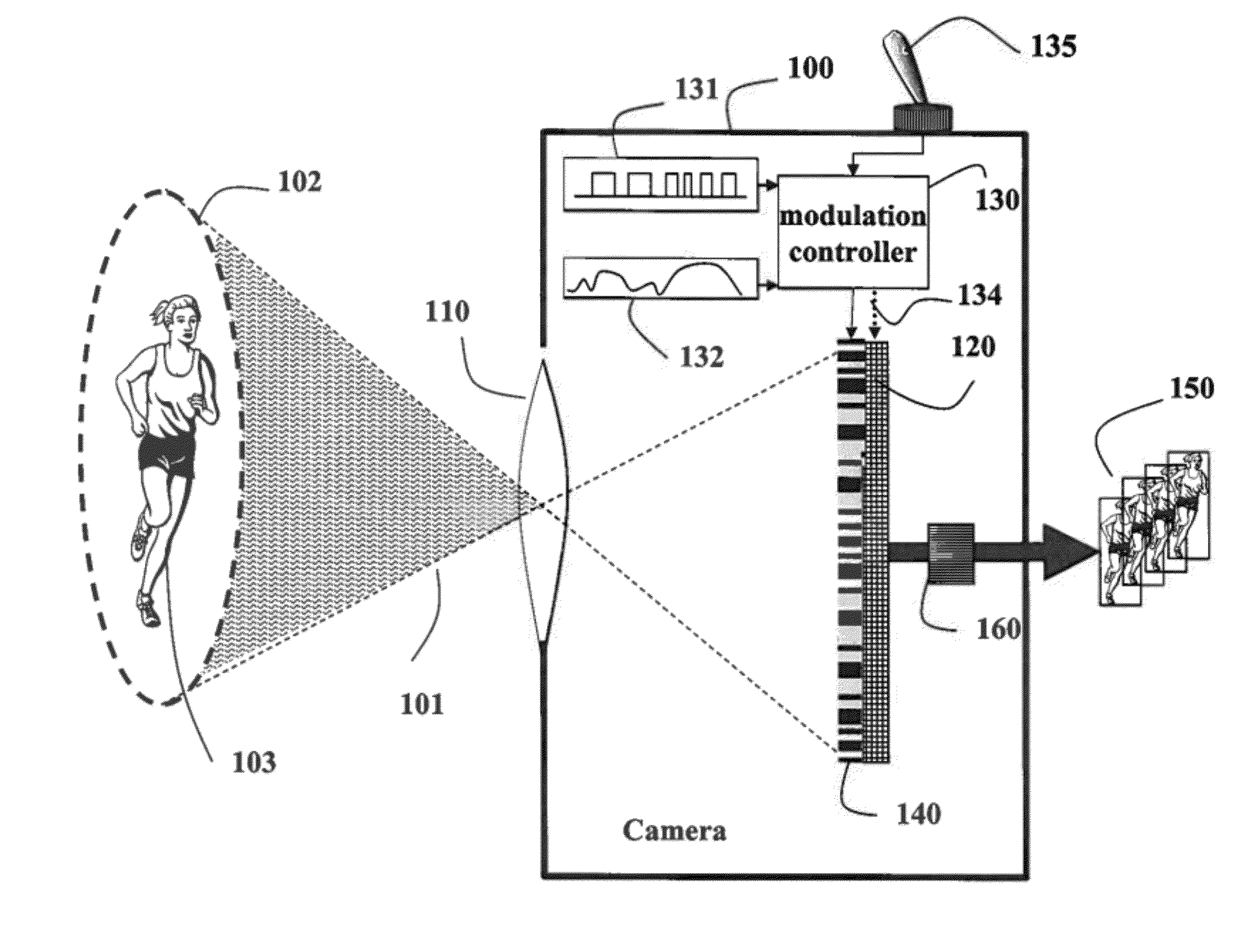
[0017]The means for modulation can be in the form of a mask arranged in an optical path between the scene and the sensor. The mask can be transmissive or reflective. Therefore, the intensities of individual pixels are individually modulated prior to integration at the sensor. Thus each frame is a coded projection of a corresponding video volume of voxels. This enables the camera to acquire a video that can be reconstructed at a perceived frame-rate that is substantially greater than the actual frame-rate of the camera. In one embodiment, the mask pixel resolution is substantially greater than the sensor pixel resolution. In another embodiment, the modulation rate is identical to the frame rate of the camera.

Problems solved by technology

However, the temporal resolutions of most conventional video camera remains limited, e.g., 30 to 60 frames per second (fps).
High speed video cameras are technically challenging and expensive because of the requirement for a high bandwidth, light efficiency, and throughput.
Unfortunately, there are fundamental limits to those methods.
While those systems demonstrate that multiple cameras can be used for temporal super-resolution, they are expensive, require multiple cameras with accurate synchronization and scales only linearly with number of cameras.
Such methods, while being very attractive in principle, have only achieved moderate success, mainly because the temporal structure of videos is not explicitly modeled, and the hardware architectures for these methods are either cumbersome and / or expensive.

Method used


Image

  • Programmable Camera and Video Reconstruction Method
  • Programmable Camera and Video Reconstruction Method
  • Programmable Camera and Video Reconstruction Method

Examples


Embodiment Construction

[0024]Programmable Pixel Compressive Video

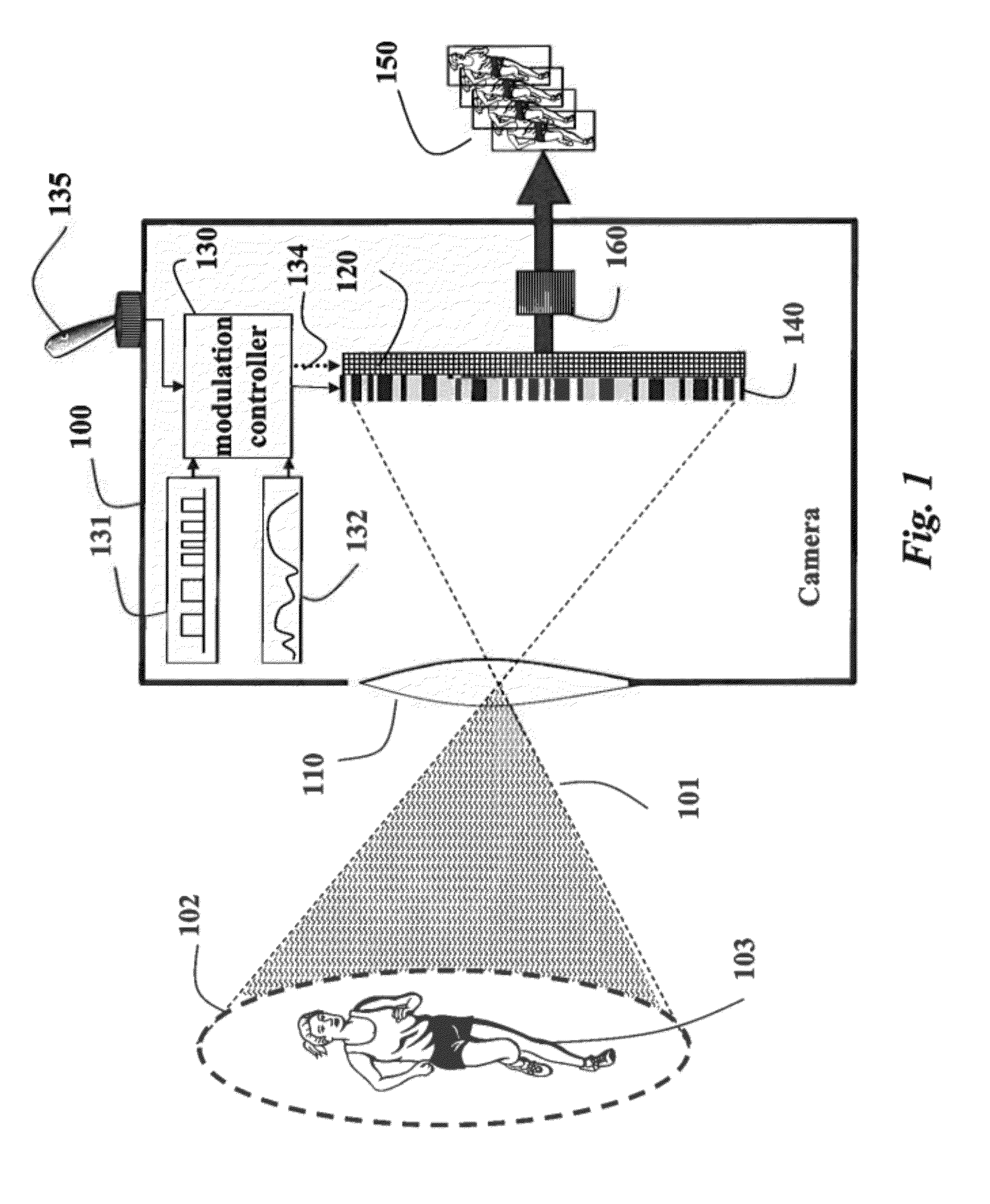
[0025]FIG. 1 is simplified schematics of a programmable pixel compressive video camera 100 according to embodiments of our invention. The camera is configured to acquire a sequence of frames of a scene as a video. The camera includes a lens 110, a sensor 120, a modulation controller 130, and a spatio-temporal mask 140.

[0026]In the preferred embodiment, the camera is a digital video camera, and the sensor includes an array of sensor pixels, e.g., 0.25 megapixel. The sensor can include red, green and blue (RGB) pixels interleaved in a Bayer filter mosaic, i.e., a color filter array (CFA), where the color pattern is GRGB). The camera acquires a sequence of low temporal resolution frames 150 at 30 frames per second (fps), which is the natural frame rate of the camera.

[0027]Mask

[0028]The mask includes an array of mask pixels, e.g., 1 megapixel. In other words, a spatial resolution (mask pixel resolution) of the mask is substantially greater than ...


PUM


Abstract

A camera for acquiring a sequence of frames of a scene as a video includes a sensor with an array of sensor pixels. Individual sensor pixels are modulated by corresponding modulation functions while acquiring each frame of the video. The modulation can be performed by a transmissive or reflective masked arranged in an optical path between the scene and the senor. The frames can be reconstructed to have a frame rate and spatial resolution substantially higher than a natural frame rate and a spatial resolution of the camera.

Description

FIELD OF THE INVENTION [0001]This invention relates generally to video cameras and video processing, and more particularly to video cameras from which varying spatio-temporal resolution videos can be reconstructed.BACKGROUND OF THE INVENTION[0002]The spatial resolution of conventional video cameras is steadily increasing, e.g., from 1 to 20 megapixel, or greater. However, the temporal resolutions of most conventional video camera remains limited, e.g., 30 to 60 frames per second (fps).[0003]High speed video cameras are technically challenging and expensive because of the requirement for a high bandwidth, light efficiency, and throughput. Usually, high speed cameras have limited memory, and a dedicated bus that directly connects the memory to the sensor. The frame rate is limited by the memory size.[0004]For example, in the Photron FastCam SA5, which is one of the most powerful high speed cameras, that amount to a maximum of three seconds of video at 7500 fps with a 1 megapixel resol...

Claims


Application Information

Patent Timeline
IPC IPC(8): H04N5/228
CPCH04N5/2254H04N5/23232H04N5/23225H04N23/55H04N23/617H04N23/951
Inventor VEERARAGHAVAN, ASHOKREDDY, DIKPAL N.AGRAWAL, AMIT
Owner MITSUBISHI ELECTRIC RES LAB INC
Learn More