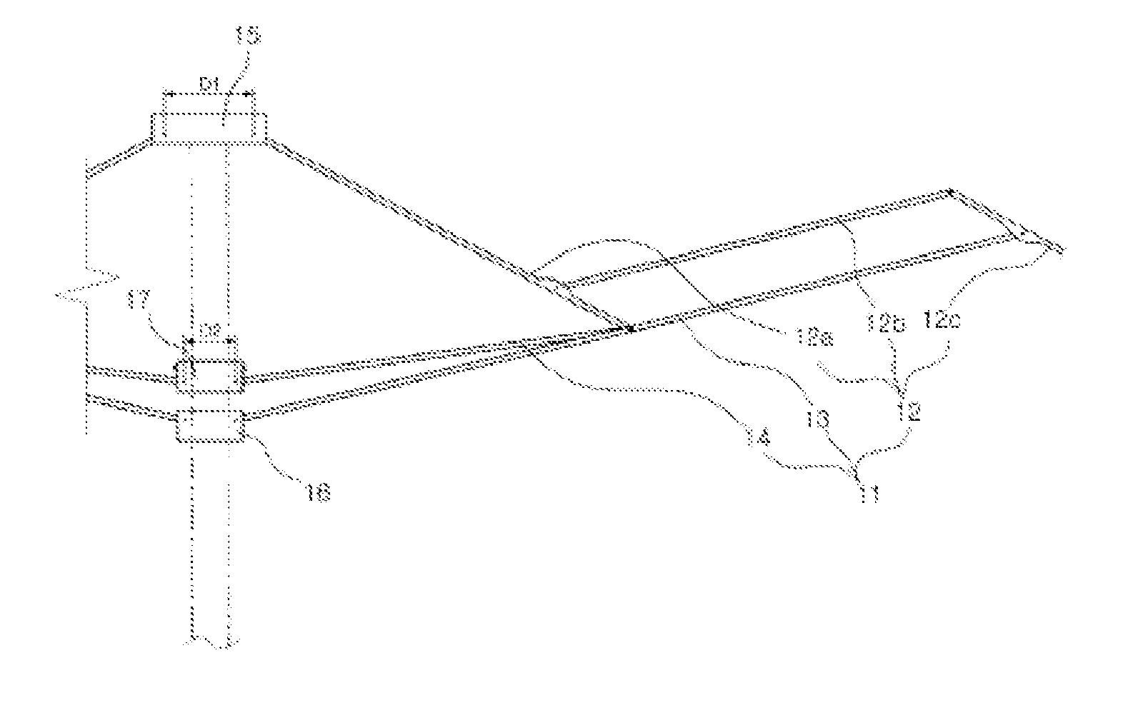

Umbrella rib assembly and foldable umbrella

Inactive Publication Date: 2012-06-28
LEE BOO IL
View PDF0 Cites 5 Cited by
  • Summary
  • Abstract
  • Description
  • Claims
  • Application Information

AI Technical Summary

Benefits of technology

[0010]An umbrella according to the present invention provides the following effects.
[0011]The umbrella has a simple configuration and produced and distributed with small expenses.
[0012]The umbrella may address concern

Problems solved by technology

This operation causes a lot of inconvenience in using the umbrellas, and particularly, a user's body or clothes become wet by the rain water present in an umbrella cloth coupled to an outer side of the umbr

Method used


Image

  • Umbrella rib assembly and foldable umbrella
  • Umbrella rib assembly and foldable umbrella
  • Umbrella rib assembly and foldable umbrella

Examples


Example

[0055]A foldable umbrella 1 according to a second exemplary embodiment of the present invention is manually spread and folded. Basic concept of the foldable umbrella 1 including the configuration of the umbrella rib assembly 11 according to the second exemplary embodiment is the same as the foldable umbrella 1 according to the first exemplary embodiment.

[0056]As shown therein, the foldable umbrella 1 according to the second exemplary embodiment of the present invention includes a handle 2. An umbrella bar 5 includes a lower bar, a lower end of which is coupled and fixed to the handle 2 and an upper bar 4 which is slidably coupled to an outside of the lower bar.

[0057]An enlarged holding bar 6 is formed in an upper end of the lower bar 3 forming the umbrella bar 5 and holds a reduced holding bar 7 formed in a lower end of the upper bar 4 to thereby control the rising of the upper bar 4. A plate spring 8, in which a projection 9 exposed to the outside through an operation hole 3a is fo...

Example

[0072]A foldable umbrella 1 according to the third exemplary embodiment of the present invention is configured to be automatically spread and manually folded. Basic concept of the foldable umbrella 1 including the configuration of the umbrella rib assembly 11 according to the third exemplary embodiment is the same as the foldable umbrella 1 according to the first exemplary embodiment.

[0073]As shown therein, the foldable umbrella 1 according to the third exemplary embodiment of the present invention includes a handle 2. An umbrella bar 5 includes a lower bar, a lower end of which is coupled and fixed to the handle 2 and an upper bar 4 which is slidably coupled to an outside of the lower bar.

[0074]An enlarged holding bar 6 is formed in an upper end of the lower bar 3 forming the umbrella bar 5 and holds a reduced holding bar 7 formed in a lower end of the upper bar 4 to thereby control the rising of the upper bar 4. A hole 4a into which a projection 26 integrally formed in a manipulat...


PUM


Abstract

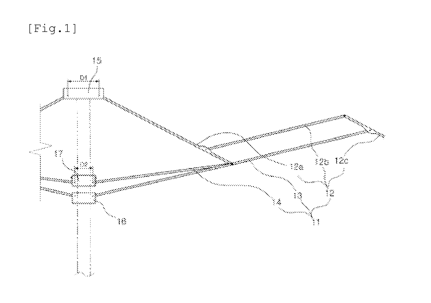
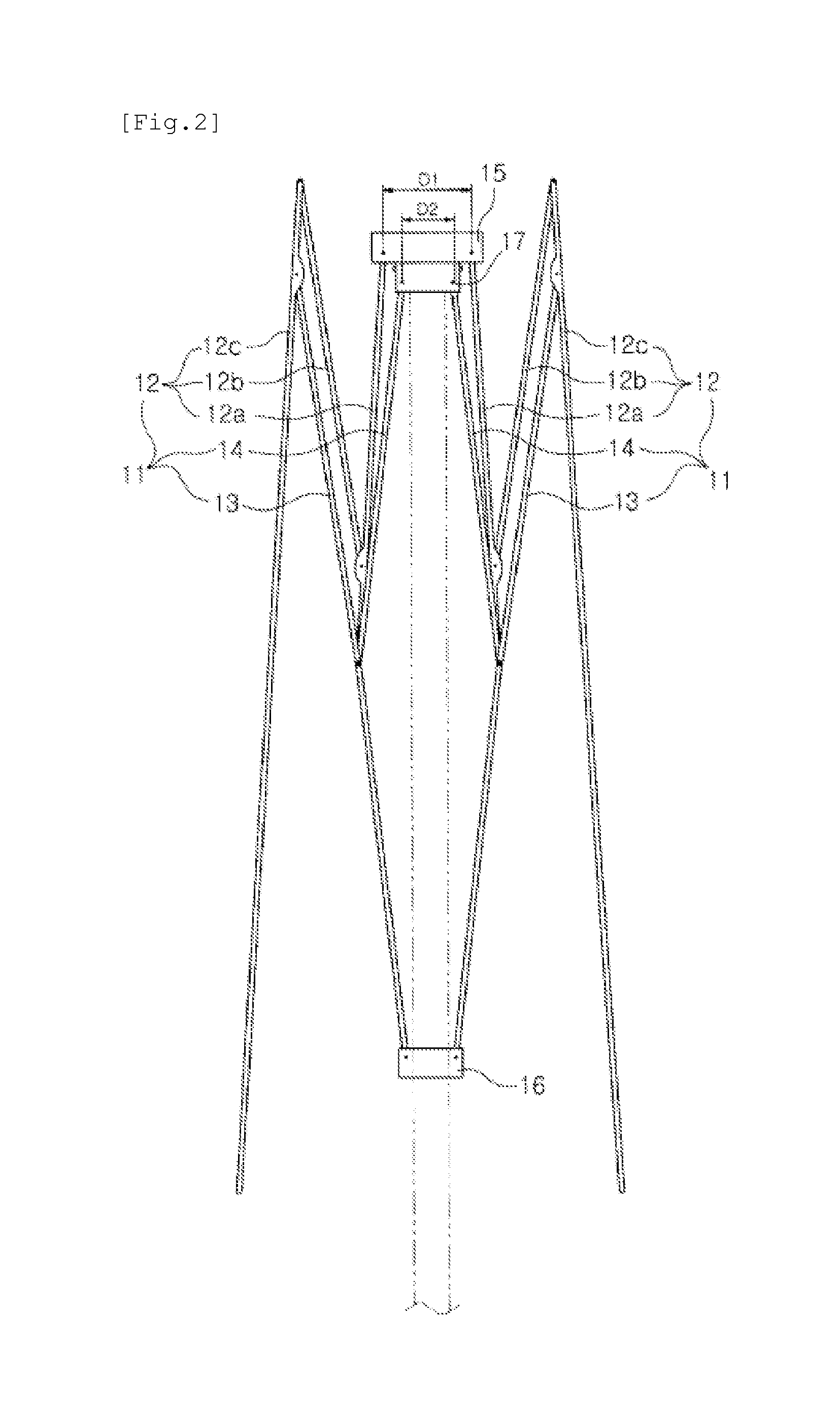
The present invention relates to an umbrella rib assembly and to a foldable umbrella. The umbrella rib assembly comprises: a plurality of main ribs, a plurality of first auxiliary ribs, and a plurality of second auxiliary ribs. Each of the main ribs includes an inner member, one end of which is coupled to a main rib fixing member such that the inner member is circumferentially rotatable; an intermediate member, one end of which is rotatably coupled, via a pin, to an upper portion from the other end of the inner member; and an outer member, one end of which is rotatably coupled, via a pin, to the other end of the intermediate member, wherein said inner member, said intermediate member, and said outer member are assembled so to be foldable. Each of the first auxiliary ribs has one end coupled via a pin to a first auxiliary rib fixing member such that the first auxiliary rib is circumferentially rotatable, each of the first auxiliary ribs has an intermediate portion to which the other end of the inner member is rotatably coupled via a pin, such that the first auxiliary rib is parallel to the intermediate member of the main rib, and the other end of each of the first auxiliary ribs is rotatably coupled, via a pin, to a lower portion from the upper end of the outer member rotatably coupled to the intermediate member of the main rib. One end of each of the second auxiliary ribs is coupled to a second auxiliary rib fixing member interposed between the main rib fixing member and the first auxiliary rib fixing member such that the second auxiliary rib is circumferentially rotatable, and the other end thereof is rotatably coupled, via a pin, to the portion to which the inner member of the main rib and an intermediate portion of the first auxiliary rib are coupled. The diameter of the joint portion of the main rib fixing member (15), to which the inner member (12a) of the main rib (12) is rotatably coupled, is significantly larger than the diameter of the joint portion of the second auxiliary rib fixing member to which the second auxiliary rib is rotatably coupled, such that the second auxiliary rib fixing member is drawn downwardly to spread the umbrella rib assembly, and pushed upwardly to fold the umbrella rib assembly. Foldable umbrellas having various configurations can be produced using the umbrella rib assembly of the present invention.

Description

TECHNICAL FIELD[0001]The present invention relates to an umbrella rib assembly and a foldable umbrella, and more particularly, to an umbrella rib assembly which is folded and spread by small force, and a foldable umbrella that is manually or automatically operated and enables a user to fold and spread by manipulating a handle by using the umbrella rib assembly and ensures convenience in use.BACKGROUND ART[0002]A user uses an umbrella to protect the body from rain. An umbrella which is widely used is classified into a long umbrella and a foldable umbrella which is portable and is folded and put in a bag.[0003]Such long and foldable umbrellas have been developed into a configuration that spreads an umbrella rib assembly by pushing a button in a handle coupled to a lower end of an umbrella bar and ensures user's convenience.[0004]To fold the long and foldable umbrellas after use, a user should grab and pull downwardly an auxiliary rib fixing member, which is provided in an upper end of...

Claims


Application Information

Patent Timeline
IPC IPC(8): A45B19/10A45B25/02
CPCA45B19/10A45B25/10A45B25/06A45B25/02
Inventor LEE, BOO IL
Owner LEE BOO IL
Learn More