
Device for adjusting rolling positions of rolling rolls constituting three-roll mandrel mill and method for manufacturing seamless pipes or tubes

a technology of rolling mills and rolling positions, which is applied in the direction of rolling mill control devices, measuring devices, manufacturing tools, etc., can solve the problems of more difficult to secure the roll-biting property of the front edge part of the pipe material in the case, more difficult to secure the circumferential length than, and achieve the effect of reducing the circumferential length of the rear edge part of the pipe or tube material

Inactive Publication Date: 2012-06-21
NIPPON STEEL CORP
View PDF2 Cites 0 Cited by
  • Summary
  • Abstract
  • Description
  • Claims
  • Application Information

AI Technical Summary

Benefits of technology

[0007]The present invention has been made to solve the above problems of prior art, and accordingly an object thereof is to provide a rolling position adjusting device capable of restraining poor roll-biting of the front edge part of a pipe or tube material rolled by a three-roll mandrel mill or capable of restraining a decrease in circumferential length of the rear edge part of the pipe or tube material.
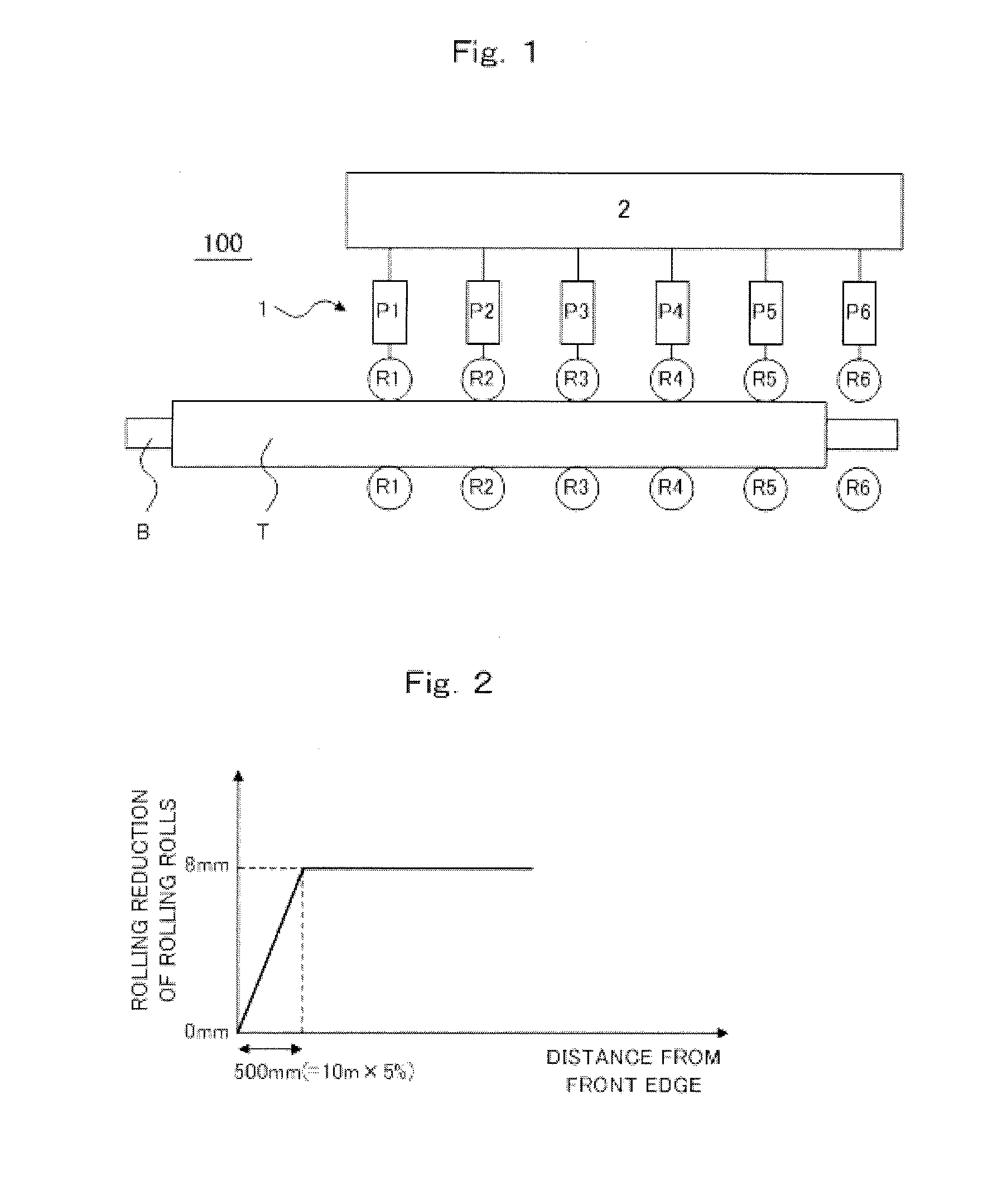
[0008]To solve the above problems, the present inventor conducted studies earnestly, and resultantly found that poor roll-biting of the front edge part of pipe or tube material can be restrained if rolling rolls are put on standby at a position at which they are open more as compared with the rolling time (at a position distant from the center of pipe or tube material) before the front edge part of pipe or tube material begins to be rolled, and the rolling rolls are moved in the closing direction (in the direction of approaching the center of pipe or tube material) immediately after the front edge part of pipe or tube material has begun to be rolled. The present invention was completed based on this new knowledge of the present inventor.
[0011]According to the above-described preferred configuration, the yield of the front edge part of pipe or tube material can be increased.
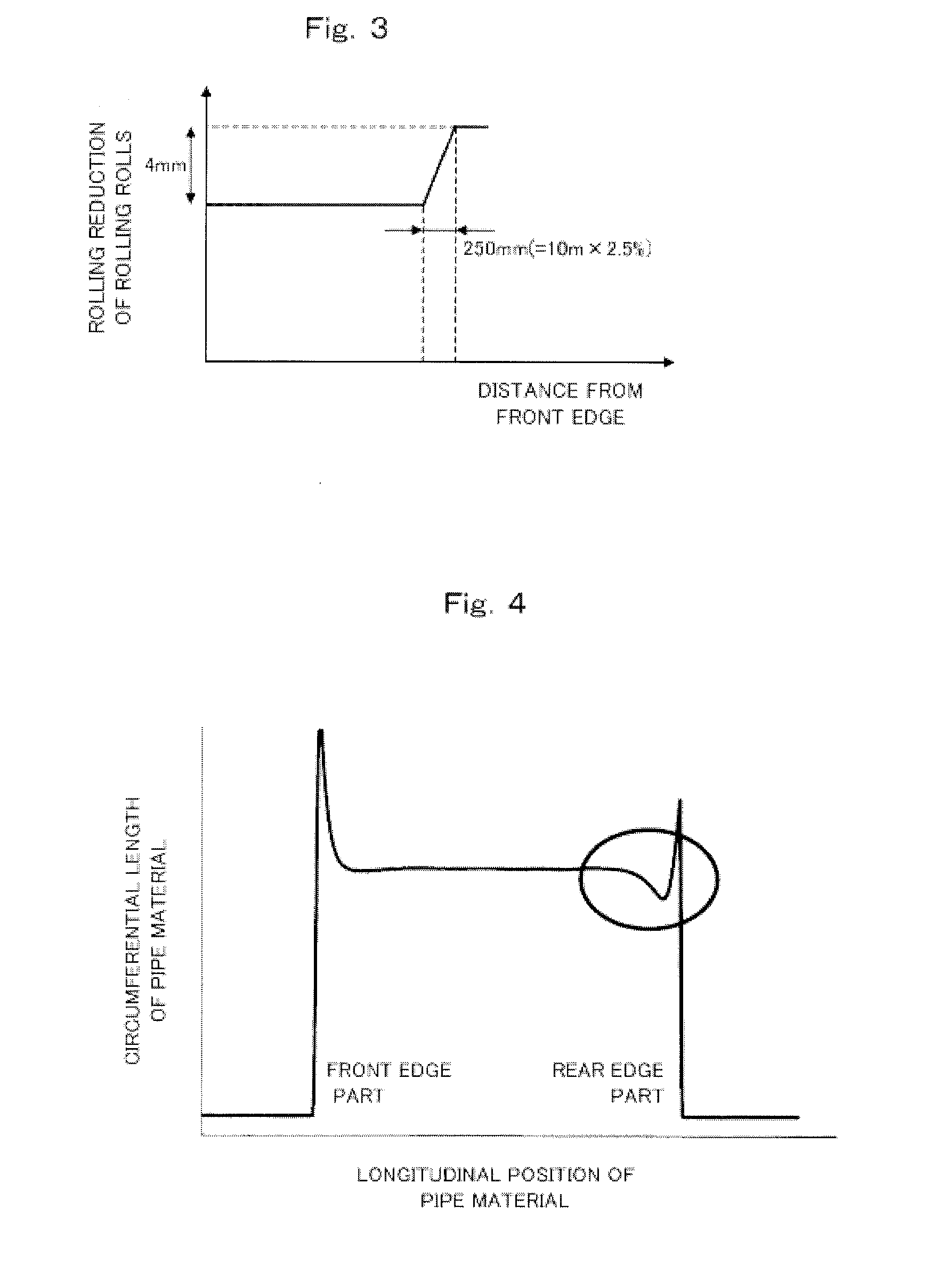
[0013]Also, to solve the above problems, the present inventor conducted studies earnestly, and resultantly found that a decrease in circumferential length of the rear edge part of pipe or tube material can be restrained if the rolling rolls are moved in the closing direction (in the direction of approaching the center of pipe or tube material) beyond the rolling position at the time when the central part of pipe or tube material is rolled immediately after the rear edge part of pipe or tube material has begun to be rolled. The present invention was completed based on this new knowledge of the present inventor.
[0016]According to the above-described preferred configuration, the yield of the rear edge part of pipe or tube material can be increased while the decrease in circumferential length of the rear edge part is restrained.
[0018]According to the present invention, poor roll-biting of the front edge part of pipe or tube material rolled by the three-roll mandrel mill can be restrained. Also, according to the present invention, the decrease in circumferential length of the rear edge part of pipe or tube material can be restrained.

Problems solved by technology

However, the increase in the working ratio of pipe material per one rolling stand poses a problem that it is difficult for the front edge part of pipe material to bite stably (to secure the roll-biting property).
Therefore, it is more difficult to secure the roll-biting property of the front edge part of pipe material in the case where the three-roll mandrel mill is used.
In particular, in the case where the three-roll mandrel mill is used, it is more difficult to secure the circumferential length than the case where the two-roll mandrel mill is used (for example, refer to JP2005-111518A, paragraph 0004).

Method used


Image

  • Device for adjusting rolling positions of rolling rolls constituting three-roll mandrel mill and method for manufacturing seamless pipes or tubes
  • Device for adjusting rolling positions of rolling rolls constituting three-roll mandrel mill and method for manufacturing seamless pipes or tubes
  • Device for adjusting rolling positions of rolling rolls constituting three-roll mandrel mill and method for manufacturing seamless pipes or tubes

Examples


Embodiment Construction

[0023]One embodiment of the present invention will now be described with reference to the accompanying drawings as appropriate.

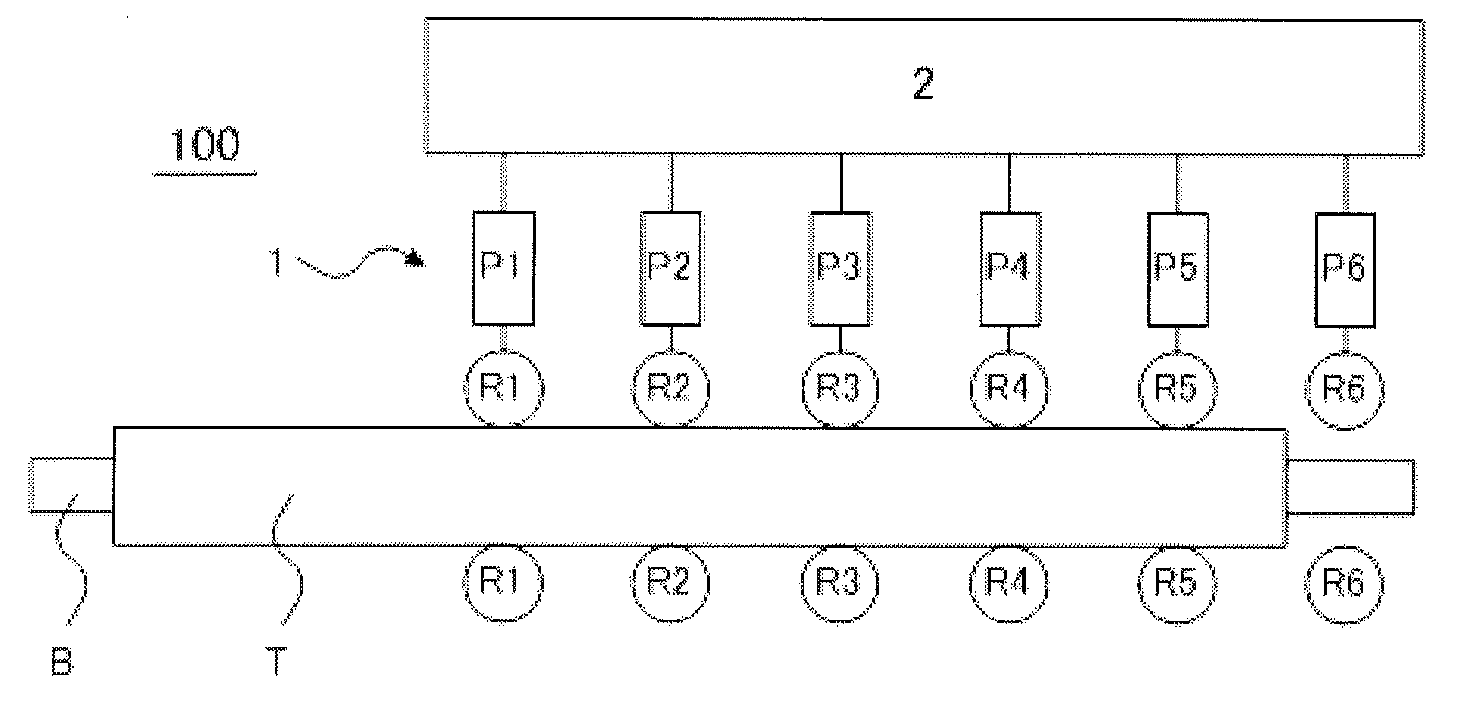
[0024]FIG. 1 is a schematic view showing a general configuration of a rolling position adjusting device for rolling rolls constituting a three-roll mandrel mill in accordance with one embodiment of the present invention.

[0025]As shown in FIG. 1, a rolling position adjusting device 100 in accordance with this embodiment is used in a three-roll mandrel mill consisting of a total of six rolling stands on each of which three rolling rolls are disposed to elongation-roll the outside surface of a pipe material T in the state in which a mandrel bar B is inserted into the pipe material T in a spit form. Describing more specifically, the rolling position adjusting device 100 in accordance with this embodiment is configured so as to be capable of adjusting the rolling positions of the rolling rolls R1 to R6 disposed on the respective rolling stands of the mandrel mill...


PUM

PropertyMeasurementUnit
speedaaaaaaaaaa
angleaaaaaaaaaa
angleaaaaaaaaaa

Abstract

A device for adjusting the rolling positions of rolling rolls and restraining poor roll-biting of the front edge part of a pipe material rolled by a three-roll mandrel mill includes pressing-down devices 1 (P1 to P6) for moving rolling rolls R1 to R6 in the rolling direction and a control unit 2 for controlling the pressing-down devices 1. Immediately after the front edge part of a pipe material T has begun to be rolled by the rolling rolls disposed on at least one rolling stand of the rolling rolls R1 to R6, the control unit 2 controls the pressing-down device 1 to move the rolling rolls in the closing direction. Preferably, the rolling rolls disposed on at least one rolling stand of the rolling rolls R1 to R6 in the closing direction are moved at a speed of 16 mm / sec or higher using the pressing-down device 1.

Description

TECHNICAL FIELD[0001]The present invention relates to a device for adjusting the rolling positions of rolling rolls constituting a three-roll mandrel mill used for manufacturing seamless pipes or tubes. More particularly, the present invention relates to a rolling position adjusting device capable of restraining poor roll-biting of the front edge part of a pipe or tube material rolled by a three-roll mandrel mill or capable of restraining a decrease in circumferential length of the rear edge part of the pipe or tube material. Hereinafter, “pipe or tube” is referred to as “pipe” when deemed appropriate.BACKGROUND ART[0002]As a mandrel mill that is equipment for manufacturing seamless pipes, a two-roll mandrel mill has conventionally been used in which two opposed rolling rolls (grooved rolls) are disposed on respective rolling stands, and are arranged alternately so that the rolling direction of rolling roll of a rolling stand is shifted by 90 degrees from that of an adjacent rolling...

Claims


Application Information

Patent Timeline
Patent Type & Authority Applications(United States)
IPC IPC(8): B21B37/58B21B37/78
CPCB21B17/04B21B37/58B21B37/62B21B37/78B21B2275/06B21B2261/10B21B2271/02B21B2273/14B21B2273/16B21B38/00
Inventor YAMANE, AKIHITOKIDANI, SHIGERU
Owner NIPPON STEEL CORP
Learn More