
Layout for parking system of decelerator for electric motor vehicle

Inactive Publication Date: 2012-06-07
HYUNDAI MOTOR CO LTD +1
View PDF3 Cites 4 Cited by
  • Summary
  • Abstract
  • Description
  • Claims
  • Application Information

AI Technical Summary

Benefits of technology

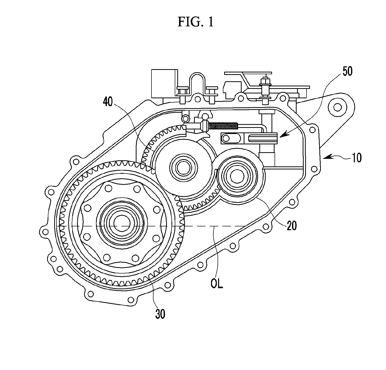
[0008]The present invention has been made in an effort to provide a layout for parking system of decelerator for an electric motor vehicle having advantages of improving layout of a parking unit and gears within a decelerator and reducing total size of the parking system.
[0009]The present invention may also reduce power loss induced by churning by disposing a parking unit above oil in the parking mechanism. Compact construction of the decelerator may be possible by reduction of shaft length and layout change, and total weight and manufacturing cost of the parking system may be possible.

Problems solved by technology

However, a typical parking mechanism brings about an increase in the size of peripheral parts, such as a case or housing, due to the overall size of the parking mechanism, and adds weight and cost to the vehicle as a whole.
Moreover, as the typical parking mechanism is disposed at a lower position, this increases the length of a manual shaft and results in a higher torsion torque.
Also, since the parking mechanism is submerged in oil, churning may induce power loss and engaged gears may be released due to sliding.

Method used


Image

  • Layout for parking system of decelerator for electric motor vehicle
  • Layout for parking system of decelerator for electric motor vehicle
  • Layout for parking system of decelerator for electric motor vehicle

Examples


Embodiment Construction

[0036]Reference will now be made in detail to various embodiments of the present invention(s), examples of which are illustrated in the accompanying drawings and described below. While the invention(s) will be described in conjunction with exemplary embodiments, it will be understood that present description is not intended to limit the invention(s) to those exemplary embodiments. On the contrary, the invention(s) is / are intended to cover not only the exemplary embodiments, but also various alternatives, modifications, equivalents and other embodiments, which may be included within the spirit and scope of the invention as defined by the appended claims.

[0037]It is understood that the term “vehicle” or “vehicular” or other similar term as used herein is inclusive of motor vehicles in general such as passenger automobiles including sports utility vehicles (SUV), buses, trucks, various commercial vehicles, watercraft including a variety of boats and ships, aircraft, and the like.

[0038]...


PUM


Abstract

A layout for parking system of decelerator for an electric motor vehicle is provided herein. More specifically, the layout includes a decelerator housing, an input gear disposed within the decelerator housing, an output gear disposed within the decelerator housing, an intermediating gear connecting the input gear and the output gear and a parking unit disposed above the input gear and selectively trammeling the intermediating gear. Further, in the present layout the parking unit is disposed above an oil line in the decelerator housing.

Description

CROSS-REFERENCE TO RELATED APPLICATION[0001]This application claims priority to and the benefit of Korean Patent Application No. 10-2010-0123050 filed in the Korean Intellectual Property Office on Dec. 3, 2010, the entire contents of which are incorporated herein by reference.BACKGROUND OF THE INVENTION[0002](a) Field of the Invention[0003]The present invention relates to a parking system. More particularly, the present invention relates to a layout for parking system of decelerator for an electric motor vehicle.[0004](b) Description of the Related Art[0005]In general, a parking mechanism is mounted in a decelerator. When a driver manipulates a shift lever, a sprag is engaged with a parking gear by a cam mounted on a parking rod to thus restrain the wheel from rotating. However, a typical parking mechanism brings about an increase in the size of peripheral parts, such as a case or housing, due to the overall size of the parking mechanism, and adds weight and cost to the vehicle as a...

Claims


Application Information

Patent Timeline
IPC IPC(8): F16H61/22
CPCF16H63/3416
Inventor KIM, KYUNGHAKIM, MIN SUNGLEE, JINSOOKKIM, YEONHOKIM, WAN SOO
Owner HYUNDAI MOTOR CO LTD
Learn More