Eureka AIR delivers breakthrough ideas for toughest innovation challenges, trusted by R&D personnel around the world.

Multi-rpo data protection

Active Publication Date: 2012-05-31
ZERTO
View PDF4 Cites 52 Cited by
  • Summary
  • Abstract
  • Description
  • Claims
  • Application Information

AI Technical Summary

Benefits of technology

[0015]Aspects of the present invention overcome drawbacks with conventional single-RPO disaster recovery systems, and provide multi-RPO disaster recovery systems, for designating multiple RPO objectives based on day and time of day, with multiple respective bandwidths allocated to the disaster recovery systems. Aspects of the present invention provide disaster recovery systems with calendar-based, or date and time-based, RPO objectives and bandwidth allocations, thereby achieving greater flexibility and cost effectiveness vis-à-vis conventional single-RPO systems.
[0016]Using the present invention, a disaster recovery system may share a link between sites for replication and applications. The disaster recovery system may set a higher RPO objective during peak times and a lower RPO objective during off-peal times, limit replication bandwidth during peak times, and relax replication bandwidth during off-peak times. The disaster recovery system may use the different RPO objectives to advantage for allowing as much bandwidth as possible, taking into account that a higher RPO objective is met during peak times, while catching up afterwards during off-peak times when the RPO objective is lower.
[0019]In accordance with an embodiment of the present invention, a disaster recovery system may set different limits for data seeding traffic vs. data replication traffic over a WAN.

Problems solved by technology

But the enterprise has acknowledged that data in the two hours immediately preceding the disaster may be lost; i.e., the acceptable loss window is two hours.
If an administrator receives a series of RPO alerts, it generally means that the bandwidth allocated to the disaster recovery system is insufficient for the RPO objective, and the RPO objective must be relaxed or additional bandwidth must be allocated.
Generally, allocating additional bandwidth to the disaster recovery system entails the expense of obtaining additional bandwidth for the overall enterprise system, in order not to degrade the enterprise production system.
Such lines are expensive, and are fully utilized only during relatively short time periods.
Maintaining high bandwidth lines for all enterprises is expensive, and does not fully utilize the lines most of the time.
Increasing the RPO results in missing alerts that should be issued.

Method used


Image

  • Multi-rpo data protection
  • Multi-rpo data protection
  • Multi-rpo data protection

Examples


Embodiment Construction

[0045]Aspects of the present invention relate to disaster recovery with multiple RPOs that are applied in accordance with a schedule of dates and times.

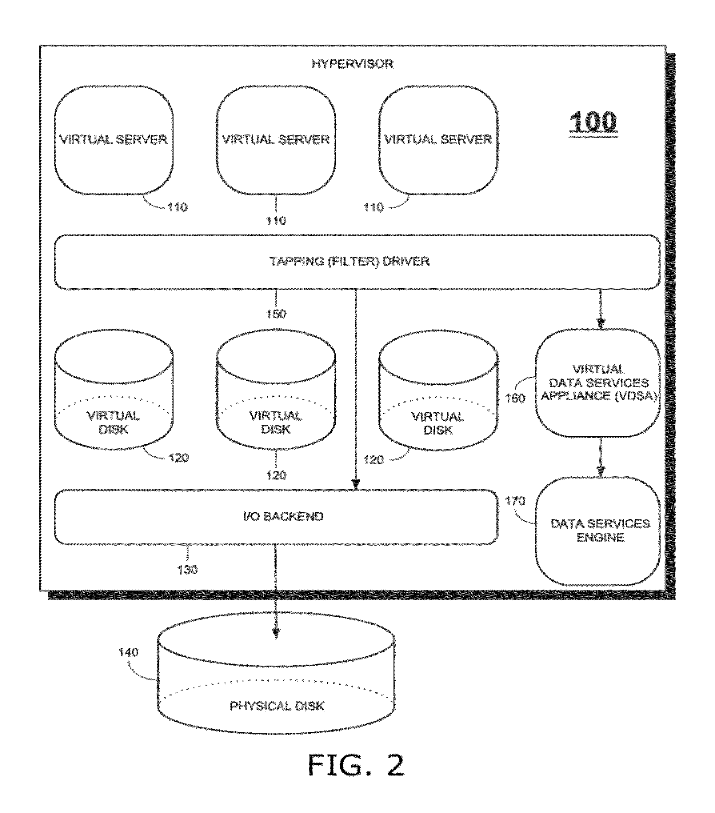
[0046]Reference is made to FIG. 2, which is a simplified block diagram of a hypervisor architecture that includes a tapping driver and a VDSA, in accordance with an embodiment of the present invention. Shown in FIG. 2 is a hypervisor 100 with three virtual servers 110, three virtual disks 120, an I / O backend 130 and a physical storage array 140. Hypervisor 100 uses a single physical server, but runs multiple virtual servers 110. Virtual disks 120 are a storage emulation layer that provide storage for virtual servers 110. Virtual disks 120 are implemented by hypervisor 100 via I / O backend 130, which connects to physical disk 140.

[0047]Hypervisor 100 also includes a tapping driver 150 installed within the hypervisor kernel. As shown in FIG. 2, tapping driver 150 resides in a software layer between virtual servers 110 and virtual disks ...


PUM


Abstract

A system for disaster recovery including a controller (i) for controlling bandwidth usage of a disaster recovery system in accordance with a plurality of recovery point objectives (RPOs), each RPO designating a maximal time loss constraint for data recovery for an enterprise production system, and a corresponding bandwidth allocation for the disaster recovery system to use in replicating data for the enterprise production system, wherein the RPOs are applied in accordance with a calendar-based schedule of dates and times, and (ii) for issuing an RPO alert when the RPO maximal time loss constraint for a current date and time is not satisfied.

Description

CROSS REFERENCES TO RELATED APPLICATIONS[0001]This application is a continuation-in-part of U.S. application Ser. No. 13 / 175,898, entitled METHODS AND APPARATUS FOR PROVIDING HYPERVISOR LEVEL DATA SERVICES FOR SERVER VIRTUALIZATION, filed on Jul. 4, 2011 by inventors Ziv Kedem, Gil Levonai, Yair Kuszpet and Chen Burshan, which is a continuation-in-part of U.S. application Ser. No. 13 / 039,446, entitled METHODS AND APPARATUS FOR PROVIDING HYPERVISOR LEVEL DATA SERVICES FOR SERVER VIRTUALIZATION, filed on Mar. 3, 2011 by inventor Ziv Kedem, which claims priority benefit of U.S. Provisional Application No. 61 / 314,589, entitled METHODS AND APPARATUS FOR PROVIDING HYPERVISOR LEVEL DATA SERVICES FOR SERVER VIRTUALIZATION, filed on Mar. 17, 2010 by inventor Ziv Kedem.FIELD OF THE INVENTION[0002]The present invention relates to data protection.BACKGROUND OF THE INVENTION[0003]Data is at the heart of every enterprise, and a core component of data center infrastructure. As data applications be...

Claims


Application Information

Patent Timeline
IPC IPC(8): G06F11/14
CPCG06F9/45533G06F2009/45579G06F11/1471G06F11/1484G06F11/2038G06F11/2048G06F2201/855G06F11/2069G06F11/2071G06F11/2082G06F11/2097G06F2201/815G06F11/2066G06F11/1451G06F11/1461G06F11/1469G06F2201/805G06F2201/84
Inventor BURSHAN, CHENSHEFI, OMRIKUSZPET, YAIR
Owner ZERTO
Why Eureka
Eureka Blog
Learn More