
Permanent Magnet Motor with Field Weakening

a permanent magnet motor and field weakening technology, applied in the direction of motor/generator/converter stopper, dynamo-electric converter control, circuit shape/form/construction, etc., can solve problems such as reducing field strength, and achieve the effect of reducing field strength, adjusting field strength, and altering the field strength of the motor

Inactive Publication Date: 2012-05-24
CURRENT MOTOR
View PDF1 Cites 35 Cited by
  • Summary
  • Abstract
  • Description
  • Claims
  • Application Information

AI Technical Summary

Benefits of technology

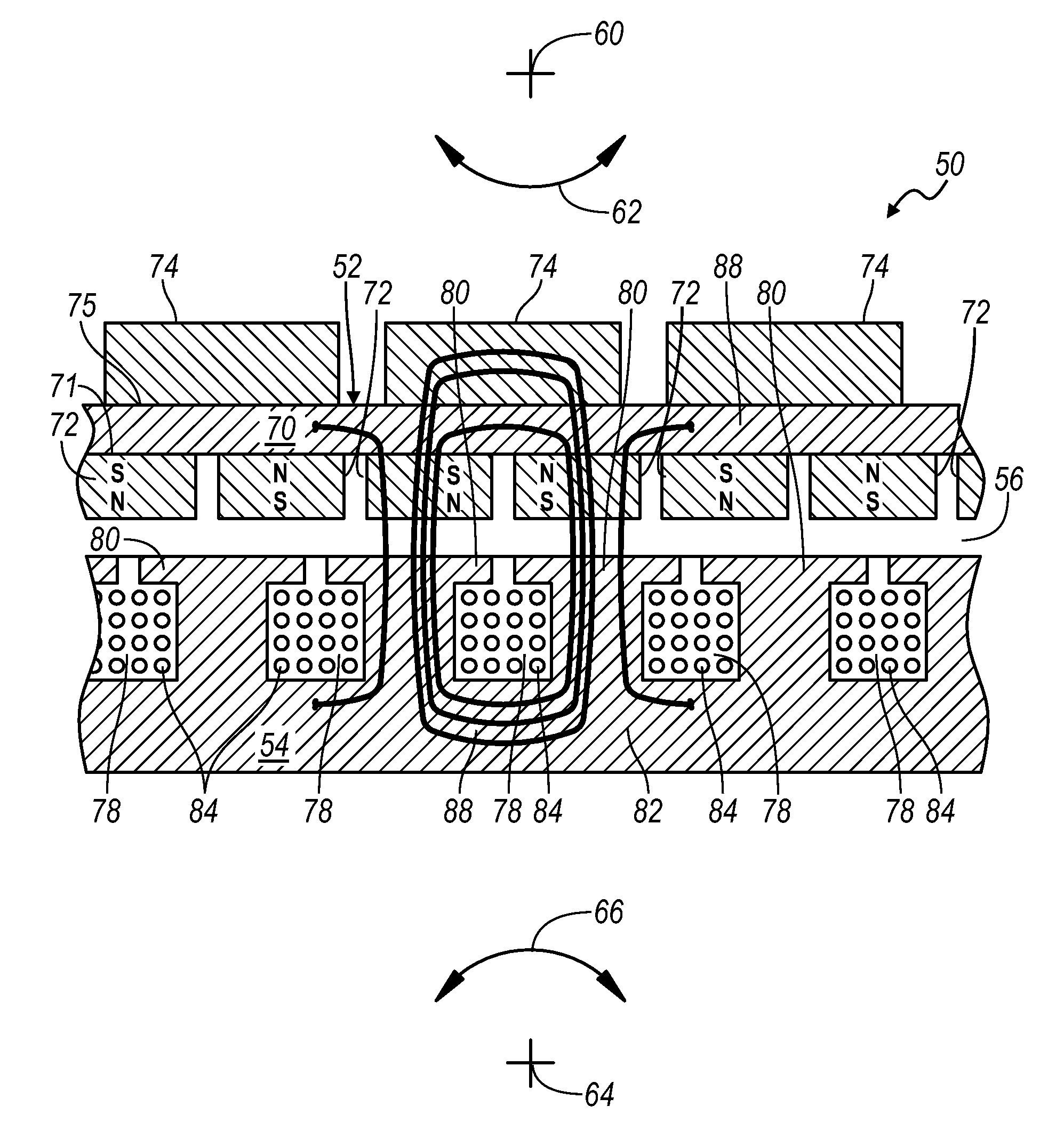
[0009]According to embodiments of the present disclosure, the field strength of the motor is altered by adjusting the reluctance of the back iron of at least one of the rotor and the stator. By providing the back iron with both a thin, fixed back iron portion, or in some embodiments none at all, and a movable back iron portion, adjustments in the field strength are possible. When the movable back iron portion is in contact with the fixed back iron, the two act as one larger back iron. When the movable back iron portion is displaced from the fixed back iron, the fixed back iron is substantially the full extent of the back iron. Almost all the magnetic flux has to pass through this thin fixed back iron section, so the fixed back iron is “saturated” or its “magnetic resistance” or reluctance goes up, thereby reducing the field strength.
[0013]In yet another embodiment, the field strength of the motor can be weakened by affecting the reluctance of the stator ring. This can be accomplished by having a fixed stator ring and one or more movable stator ring segments. Because the stator is not rotating, an actuator is used to cause the movable stator ring segments to separate from the fixed stator ring.

Problems solved by technology

Almost all the magnetic flux has to pass through this thin fixed back iron section, so the fixed back iron is “saturated” or its “magnetic resistance” or reluctance goes up, thereby reducing the field strength.

Method used


Image

  • Permanent Magnet Motor with Field Weakening
  • Permanent Magnet Motor with Field Weakening
  • Permanent Magnet Motor with Field Weakening

Examples


Embodiment Construction

[0030]While the best mode has been described in detail with respect to particular embodiments, those familiar with the art will recognize various alternative designs and embodiments within the scope of the following claims. While various embodiments may have been described as providing advantages or being preferred over other embodiments with respect to one or more desired characteristics, as one skilled in the art is aware, one or more characteristics may be compromised to achieve desired system attributes, which depend on the specific application and implementation. These attributes include, but are not limited to: cost, strength, durability, life cycle cost, marketability, appearance, packaging, size, serviceability, weight, manufacturability, ease of assembly, etc. The embodiments described herein that are characterized as less desirable than other embodiments or prior art implementations with respect to one or more characteristics are not outside the scope of the disclosure and...


PUM


Abstract

A permanent-magnet electrical machine is disclosed in which the rotor has a fixed back iron and movable back iron segments. When the movable back iron segments are in a first position, such as in contact with the fixed back iron, the field strength is high. When the movable back iron segments are in a second position in which the movable back iron segments are displaced away from the fixed back iron, the field strength is low. The ability to weaken the field strength causes the constant-power, speed ratio to be increased and thereby increases the utility of the motor for applications in which a wide speed range is desired. The disclosure applies to both permanent-magnet motors and generators. In an alternative embodiment, the stator ring is provided with a fixed portion and at least one movable stator segment.

Description

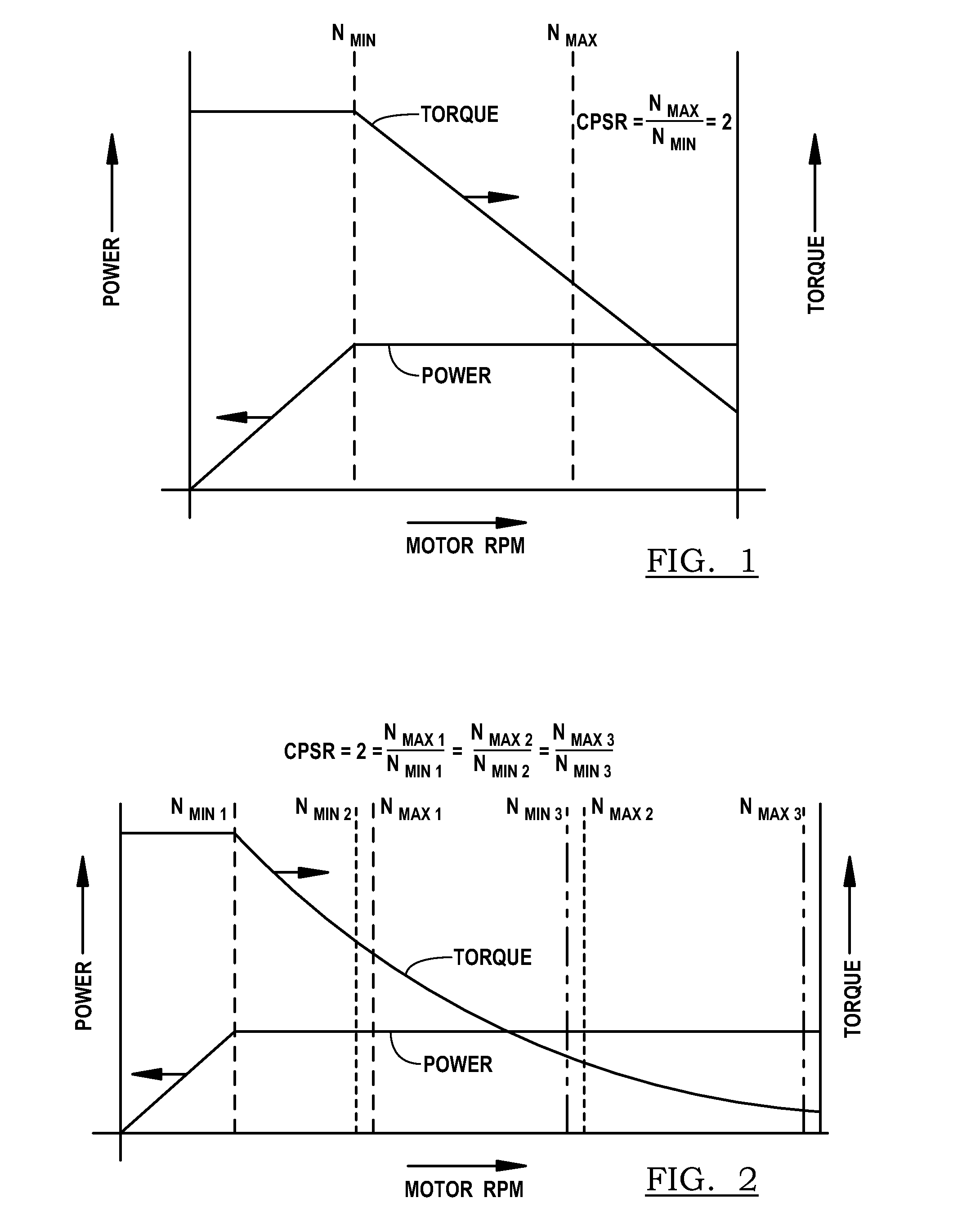
CROSS-REFERENCE TO RELATED APPLICATIONS[0001]This application claims the benefit of U.S. provisional Application No. 61 / 421,952 filed Dec. 10, 2010, the disclosure of which is incorporated in its entirety by reference herein.TECHNICAL FIELD[0002]The present disclosure relates to magnetic field weakening in a permanent magnet motor.BACKGROUND[0003]There is a need for efficient electrical machines that have high torque capability over a large speed range and the ability to control machine speed, in particular for electrical drives for vehicles, such as electric or hybrid vehicles, or other electric generation applications which require high torque at zero and low speed.[0004]For purposes of providing traction power, such as in electric vehicles, it is desirable to have an electric motor with a high constant power speed ratio (CPSR). Referring to FIG. 1, torque and power as a function of speed is shown for an electric motor. At low speed, high torque is available with such torque assis...

Claims


Application Information

Patent Timeline
IPC IPC(8): H02P7/00H02P9/40H02K1/28
CPCH02K21/028H02P6/08H02P23/0036B60L15/20Y02T10/7275Y02T10/644Y02T10/641Y02T10/648B60L2220/50Y02T10/72H02P23/0004Y02T10/64H02P6/10
Inventor KAUPPI, ERIK
Owner CURRENT MOTOR
Learn More