
Method and apparatus for securing an object to bone, including the provision and use of a novel suture assembly for securing suture to bone

a technology of bone splint and bone, applied in the field of surgical methods and equipment, can solve the problems of inability to scale the suture anchor down to a size, inability to secure the object to bone, and inability to expand the anchor properly within the bone hole,

Active Publication Date: 2012-05-10
CONMED CORP
View PDF5 Cites 141 Cited by
  • Summary
  • Abstract
  • Description
  • Claims
  • Application Information

AI Technical Summary

Problems solved by technology

(i) various difficulties and / or inconveniences associated with a particular manner of securing the suture anchor to the bone (e.g., screw-type suture anchors require rotational motion, toggle-type suture anchors require toggling within a hole formed in the bone, expansion-type screw anchors require some sort of anchor deformation within a hole formed in the bone, etc.);
(ii) difficulties in ensuring that the body of the suture anchor is securely attached to the bone (e.g., toggle-type suture anchors can sometimes fail to properly set in a bone hole and may “skid” back out of the bone hole, expansion-type suture anchors may not expand properly within the bone hole and may pull back out of the bone hole, etc.);
(iv) an inability to scale the suture anchor down to a size small enough to allow the suture anchor to be used in and around delicate anatomical structures;
(vi) inadequate holding power (e.g., limits to the holding strength which can be provided by a screw-type suture anchor, or the holding strength which can be provided by a toggle-type suture anchor, etc.); and / or
(vii) inconveniences associated with attaching the suture to the suture anchor (either during manufacture or at the time of use), etc.

Method used


Image

  • Method and apparatus for securing an object to bone, including the provision and use of a novel suture assembly for securing suture to bone
  • Method and apparatus for securing an object to bone, including the provision and use of a novel suture assembly for securing suture to bone
  • Method and apparatus for securing an object to bone, including the provision and use of a novel suture assembly for securing suture to bone

Examples


Embodiment Construction

The Novel Suture Assembly in General

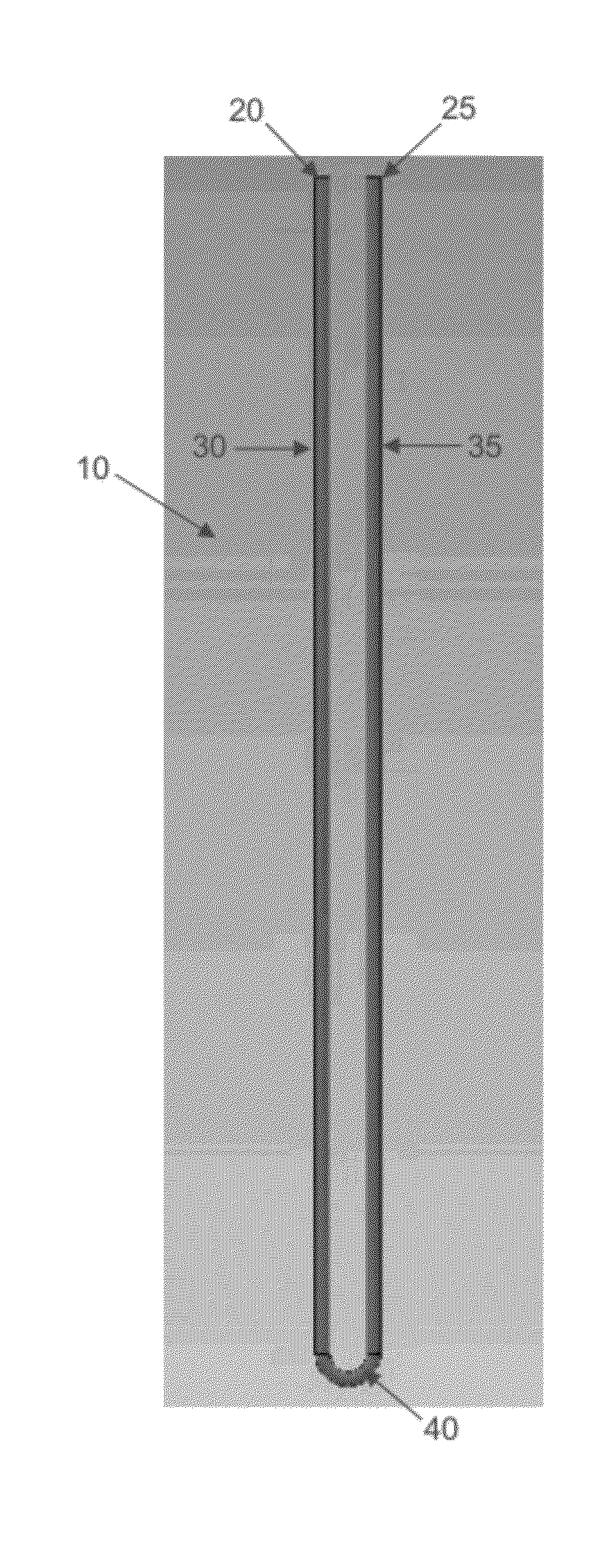
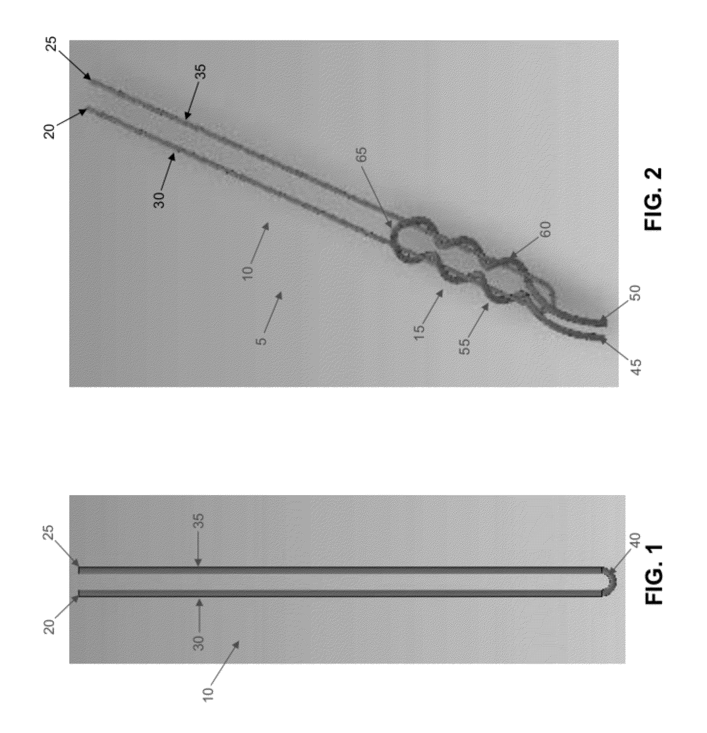
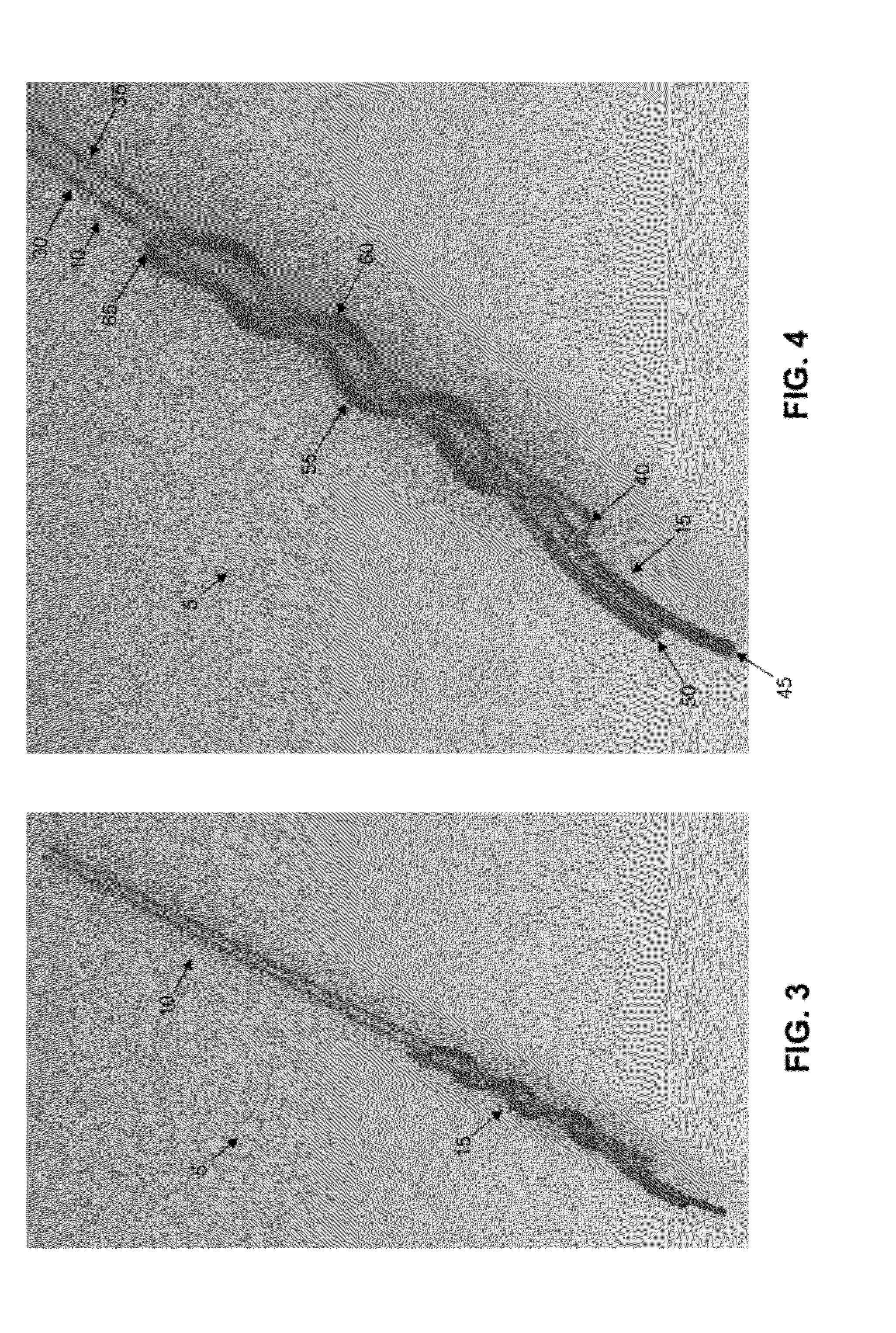
[0058]Looking first at FIGS. 1 and 2, there is shown a novel suture assembly 5 for securing suture to bone, such that the suture may be used to secure an object (e.g., soft tissue) to the bone.

[0059]More particularly, novel suture assembly 5 generally comprises a first length of suture (“first suture”) 10 (FIGS. 1 and 2) and a second length of suture (“second suture”) 15 (FIG. 2).

[0060]First suture 10 comprises a first end 20 and second end 25 such that when first suture 10 is folded back on itself, it forms a first arm 30 which includes first end 20, and a second arm 35 which includes second end 25, with first arm 30 being connected to second arm 35 via a bridge 40.

[0061]Second suture 15 comprises a first end 45 and second end 50 such that when second suture 15 is folded back on itself, it forms a first arm 55 which includes first end 45, and a second arm 60 which includes second end 50, with first arm 55 being connected to second arm 60 via a br...


PUM


Abstract

A suture assembly comprising:a first suture having a generally U-shaped configuration comprising a first arm, a second arm and a bridge connecting the first arm to the second arm;a second suture comprising a first arm, a second arm and a bridge connecting the first arm to the second arm;the first arm of the second suture being wrapped around the first arm of the first suture in a first direction, and the second arm of the second suture being wrapped around the second arm of the first suture in a second, opposite direction;the suture assembly being capable of assuming (i) a longitudinally-extended, radially-contracted first configuration, and (ii) a longitudinally-contracted, radially-expanded second configuration.

Description

REFERENCE TO PENDING PRIOR PATENT APPLICATIONS[0001]This patent application claims benefit of:[0002](i) pending prior U.S. Provisional Patent Application Ser. No. 61 / 410,027, filed Nov. 4, 2010 by Dennis McDevitt et al. for APPARATUS ASSEMBLY AND METHOD FOR SOFT TISSUE REPAIR (Attorney's Docket No. INCUMED-16 PROV);[0003](ii) pending prior U.S. Provisional Patent Application Ser. No. 61 / 419,334, filed Dec. 3, 2010 by Dennis McDevitt et al. for APPARATUS ASSEMBLY AND METHOD FOR SOFT TISSUE REPAIR (Attorney's Docket No. INCUMED-17 PROV);[0004](iii) pending prior U.S. Provisional Patent Application Ser. No. 61 / 422,859, filed Dec. 14, 2010 by Dennis McDevitt et al. for APPARATUS ASSEMBLY AND METHOD FOR SOFT TISSUE REPAIR (Attorney's Docket No. INCUMED-18 PROV); and[0005](iv) pending prior U.S. Provisional Patent Application Ser. No. 61 / 443,325, filed Feb. 16, 2011 by Dennis McDevitt et al. for APPARATUS ASSEMBLY AND METHOD FOR SOFT TISSUE REPAIR (Attorney's Docket No. INCUMED-21 PROV).[...

Claims


Application Information

Patent Timeline
Patent Type & Authority Applications(United States)
IPC IPC(8): A61B17/04
CPCA61B17/0401A61B17/1796A61B2017/0406A61B2017/00429A61B2017/0496A61B17/0482A61B2017/0409A61B2017/06171A61B17/04A61B17/84A61B17/11
Inventor MCDEVITT, DENNISNOVAK, VINCENT
Owner CONMED CORP
Learn More