


Quick Research
Generate reliable direction feasibility study reports for your R&D in just a few steps.

Technical Q&A
Discover and master advanced knowledge NOW. Basics, ideas, possibilities, all at once.

Find Solutions
As an expert in R&D theories, this can generate solutions to your technical problems instantly.

Evaluate Feasibility
Analyze your overall solution with one click, know your potential R&D risks in advance.

Monitor Landscape
Get weekly tech updates, stay abreast of the latest tech innovations and key insights.
Charging system and method for controlling charging system
- Summary
- Abstract
- Description
- Claims
- Application Information
AI Technical Summary
Benefits of technology
Problems solved by technology
Method used
Image

Examples
first embodiment
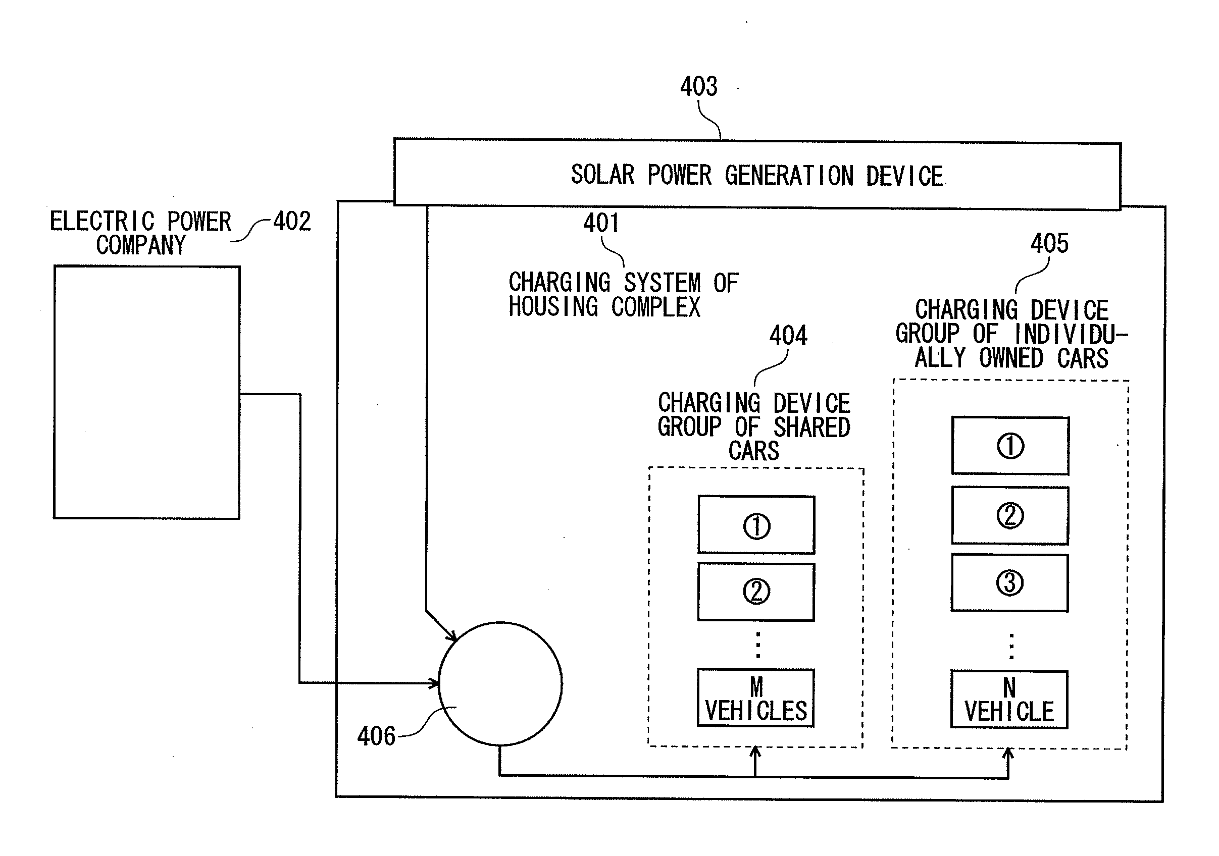
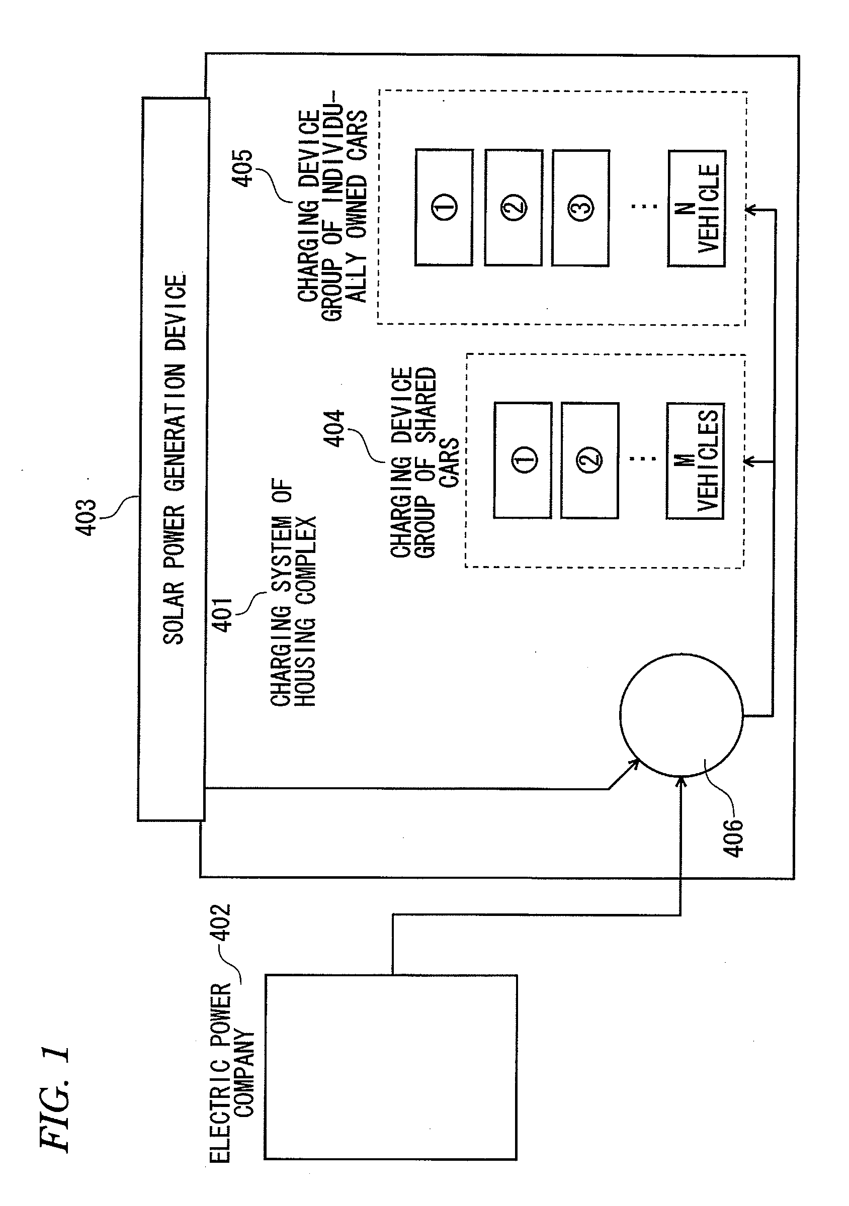
[0060]FIG. 1 is a diagram schematically illustrating a configuration of a charging system and its periphery according to a first embodiment of the present invention. In the figure, a charging system 401 is installed at a housing complex and charges electric vehicles using electric power supplied from an electric power company 402 and electric power generated by a solar power generation device 403 which is installed on a roof or the like of the housing complex.
[0061]In order to charge the electric vehicles, the charging system 401 includes a charging device group 404 which is provided to charge shared cars (M) used by residents for car sharing at the housing complex and charges electric vehicles which are parked in a car sharing parking area, and a charging device group 405 which charges electric vehicles (N) owned by individual residents parked in an individual parking area at the housing complex (generally, M<N).
[0062]Here, the electric power supplied from the electric power compan...
second embodiment
[0104]FIG. 6 is a block diagram schematically illustrating a configuration of a charging system according to a second embodiment of the present invention. In the figure, the same reference numerals are given to the same units as in the charging system in FIG. 2, and detailed description thereof will be omitted. Further, in the present embodiment, vehicles parked in a parking area are also divided into a first vehicle group owned by individuals and a second vehicle group shared by a plurality of persons.
[0105]A charging system 70 according to the present embodiment includes a generated electricity amount measuring device 71 which measures electric power generated by a natural energy generation device 200 such as a solar power generation device or a wind power generation device, in addition to the electric power usage measuring device 2, the charging control device 3, the first charging device 5 and the second charging device 6. The charging system 70 measures available electric power...
third embodiment
[0128]FIG. 10 is a block diagram schematically illustrating a configuration of a charging system according to a third embodiment of the present invention. In the figure, the same reference numerals are given to the same units as in the charging system in FIG. 2, and detailed description thereof will be omitted. Further, in the present embodiment, vehicles parked in a parking area are also divided into a first vehicle group owned by individuals and a second vehicle group shared by a plurality of persons.
[0129]A charging system 80 according to the present embodiment includes an electric power usage measuring device 81 which measures usage electric power different from the charging of the first charging device 5 and the second charging device 6, in addition to the electric power usage measuring device 2, the charging control device 3, the first charging device 5 and the second charging device 6. The charging system 80 measures available electric power for charging the electric vehicles...
PUM
 Abstract
Description
Claims
Application Information
 - R&D Engineer
- R&D Manager
- IP Professional
- Industry Leading Data Capabilities
- Powerful AI technology
- Patent DNA Extraction
Browse by: Latest US Patents, China's latest patents, Technical Efficacy Thesaurus, Application Domain, Technology Topic, Popular Technical Reports.
© 2024 PatSnap. All rights reserved.Legal|Privacy policy|Modern Slavery Act Transparency Statement|Sitemap|About US| Contact US: help@patsnap.com