
Low-latency fusing of virtual and real content

a technology applied in the field of low-latency fusing of virtual and real content, can solve problems such as inherent latency in the system

Active Publication Date: 2012-05-03
MICROSOFT TECH LICENSING LLC
View PDF6 Cites 435 Cited by
  • Summary
  • Abstract
  • Description
  • Claims
  • Application Information

AI Technical Summary

Benefits of technology

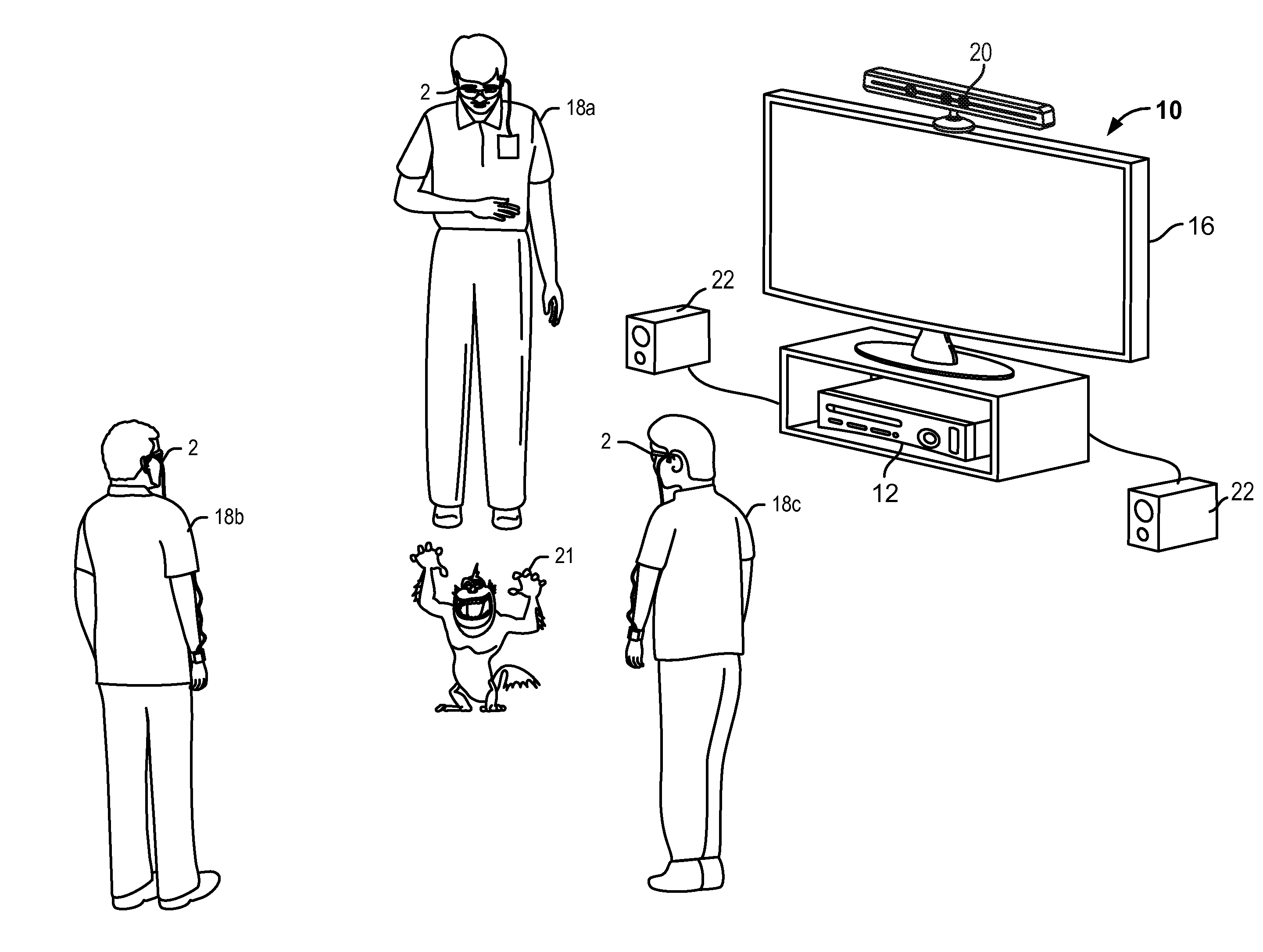
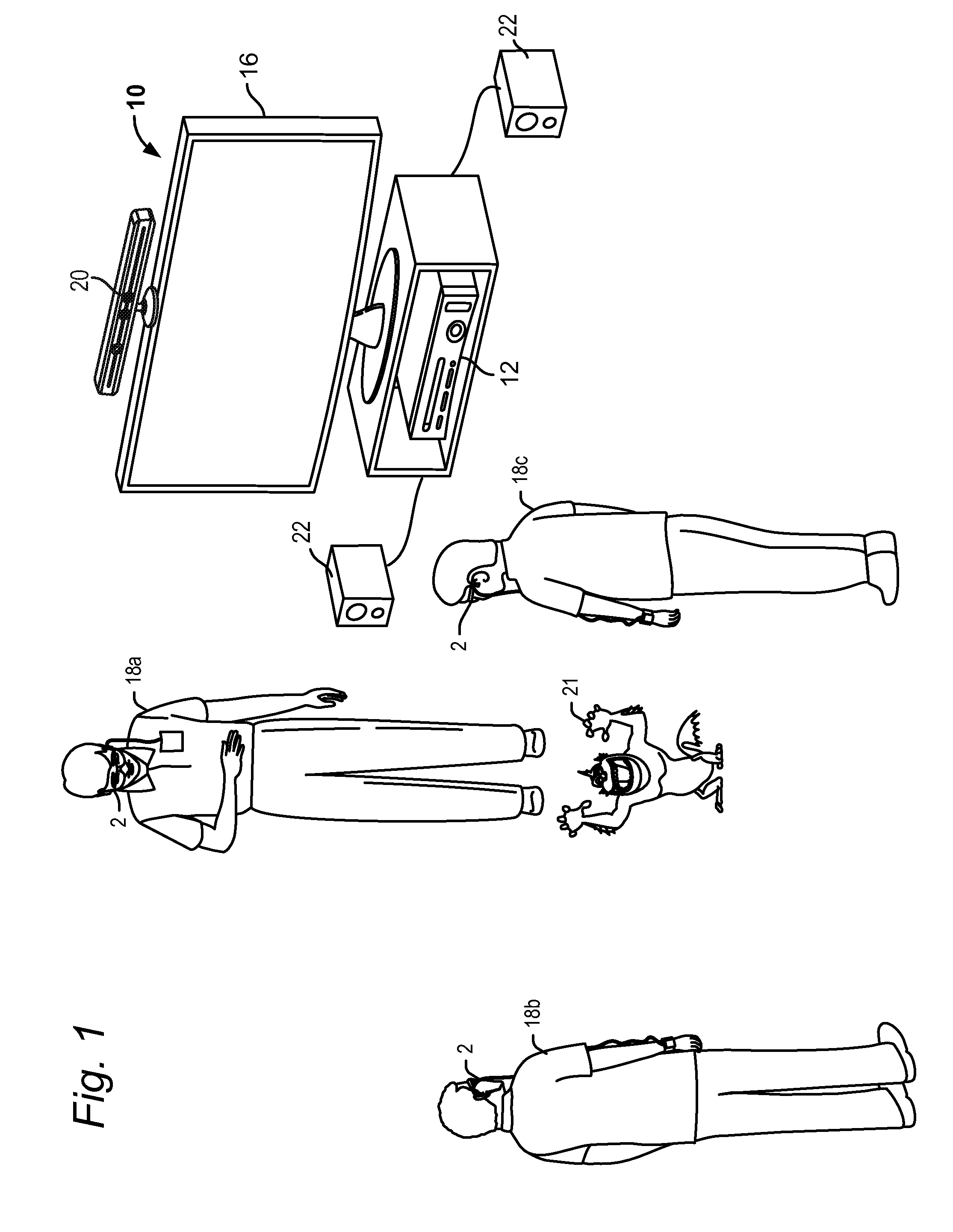
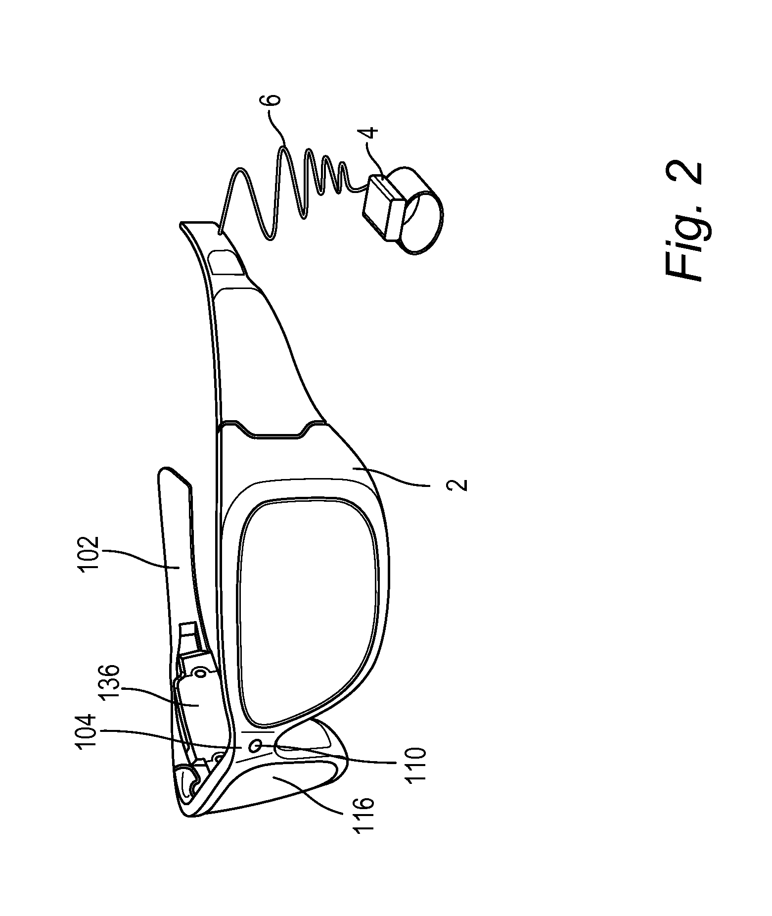
[0003]The technology described herein provides a system for fusing virtual content with real content to provide a mixed reality experience for one or more users. The system includes mobile display devices wirelessly communicating with a powerful hub computing system. Each mobile display device may include a mobile processing unit coupled to a head mounted display device (or other suitable apparatus) having a display element. Each user wears a head mounted display device which allows the user to look through the display element at the room. The display device allows actual direct viewing of the room and the real world objects in the room through the display element. The display element also provides the ability to project virtual images into the field of view of the user such that the virtual images appear to be in the room. The system automatically tracks where the user is looking so that the system can determine where to insert the virtual image in the field of view of the user. Once the system knows where to project the virtual image, the image is projected using the display element.
[0005]It takes time to generate and update the positions of all objects in an environment and it takes time to render the virtual objects from the perspective of each user. These operations thus introduce inherent latency in the system. However, over small time periods such as a few frames of data, movements tend to be generally smooth and steady. Therefore in accordance with the present technology, data from current and past time periods may be examined so as to extrapolate the positions of objects, and each user's view of those objects, into the future. Using this future prediction of the final scene map and user field of view of the scene map, virtual images of the scene may be displayed to each user without any latency. The prediction of the final scene map and user field of view may be updated throughout a frame to narrow the possible solutions until it is time to send a rendered image to the head mounted display device of each user to display the virtual elements of the mixed reality experience.

Problems solved by technology

These operations thus introduce inherent latency in the system.

Method used


Image

  • Low-latency fusing of virtual and real content
  • Low-latency fusing of virtual and real content
  • Low-latency fusing of virtual and real content

Examples


Embodiment Construction

[0023]A system is disclosed herein that can fuse virtual objects with real objects. In one embodiment, the system includes a head mounted display device and a processing unit in communication with the head mounted display device worn by each of one or more users. The head mounted display device includes a display that allows a direct view of real world objects through the display. The system can project virtual images on the display that are viewable by the person wearing the head mounted display device while that person is also viewing real world objects through the display. Multiple users may further see the same virtual object from their different perspectives, as if each is looking at a real world object from their different positions. Various sensors are used to detect position and orientation of the one or more users in order to determine where to project the virtual images.

[0024]One or more of the sensors are used to scan the neighboring environment and build a model of the s...


PUM


Abstract

A system that includes a head mounted display device and a processing unit connected to the head mounted display device is used to fuse virtual content into real content. In one embodiment, the processing unit is in communication with a hub computing device. The processing unit and hub may collaboratively determine a map of the mixed reality environment. Further, state data may be extrapolated to predict a field of view for a user in the future at a time when the mixed reality is to be displayed to the user. This extrapolation can remove latency from the system.

Description

BACKGROUND[0001]Mixed reality is a technology that allows virtual imagery to be mixed with a real world physical environment. For example, a mixed reality system can be used to insert an image of a dinosaur into a user's view of a room so that the user sees a dinosaur walking in the room.[0002]A significant drawback of conventional mixed reality systems is latency. When a user turns his head, the user's view of the real world changes pretty much instantaneously. However, in conventional mixed reality systems, it takes time for the sensors to sense the new image data and render the graphics image for display to the head gear worn by the user. While recent advances have minimized this latency, it is still anywhere from one to a few frames. This visual mismatch between the actual and virtual views can cause discomfort and disorientation for users. Conventional mixed reality systems have also relied on powerful but large processing systems to perform the bulk of the processing including...

Claims


Application Information

Patent Timeline
IPC IPC(8): G09G5/00
CPCG02B27/0093G02B27/017G02B2027/0134G02B2027/0138G02B2027/014G06F3/012G06F3/013G06T19/006G06T2219/024G06T1/20G06F3/0304G02B27/0172G09G2340/125G09G3/007G06T15/20G09G2370/02G06T7/70
Inventor BAR-ZEEV, AVIGOOSSEN, J. ANDREWTARDIF, JOHNGROSSMAN, MARK S.SINGH, HARJIT
Owner MICROSOFT TECH LICENSING LLC
Learn More