
Stationary actuator device for controlling the pitch of fan blades of a turboprop

a turboprop and actuator technology, applied in the field of turboprops, can solve the problems of difficult installation of actuators that are secured to a stationary structural element, affecting the operation of the turboprop, and manifesting practical problems of implementation

Active Publication Date: 2012-04-26
SN DETUDE & DE CONSTR DE MOTEURS DAVIATION S N E C M A
View PDF18 Cites 16 Cited by
  • Summary
  • Abstract
  • Description
  • Claims
  • Application Information

AI Technical Summary

Benefits of technology

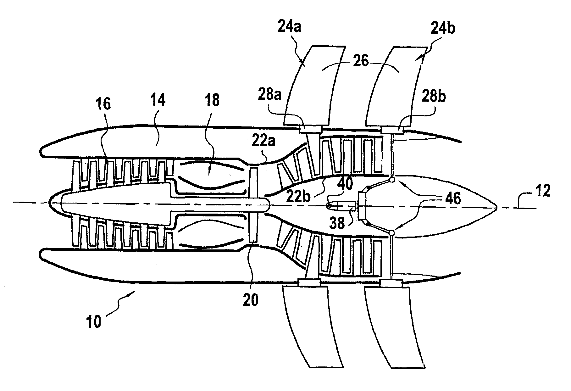
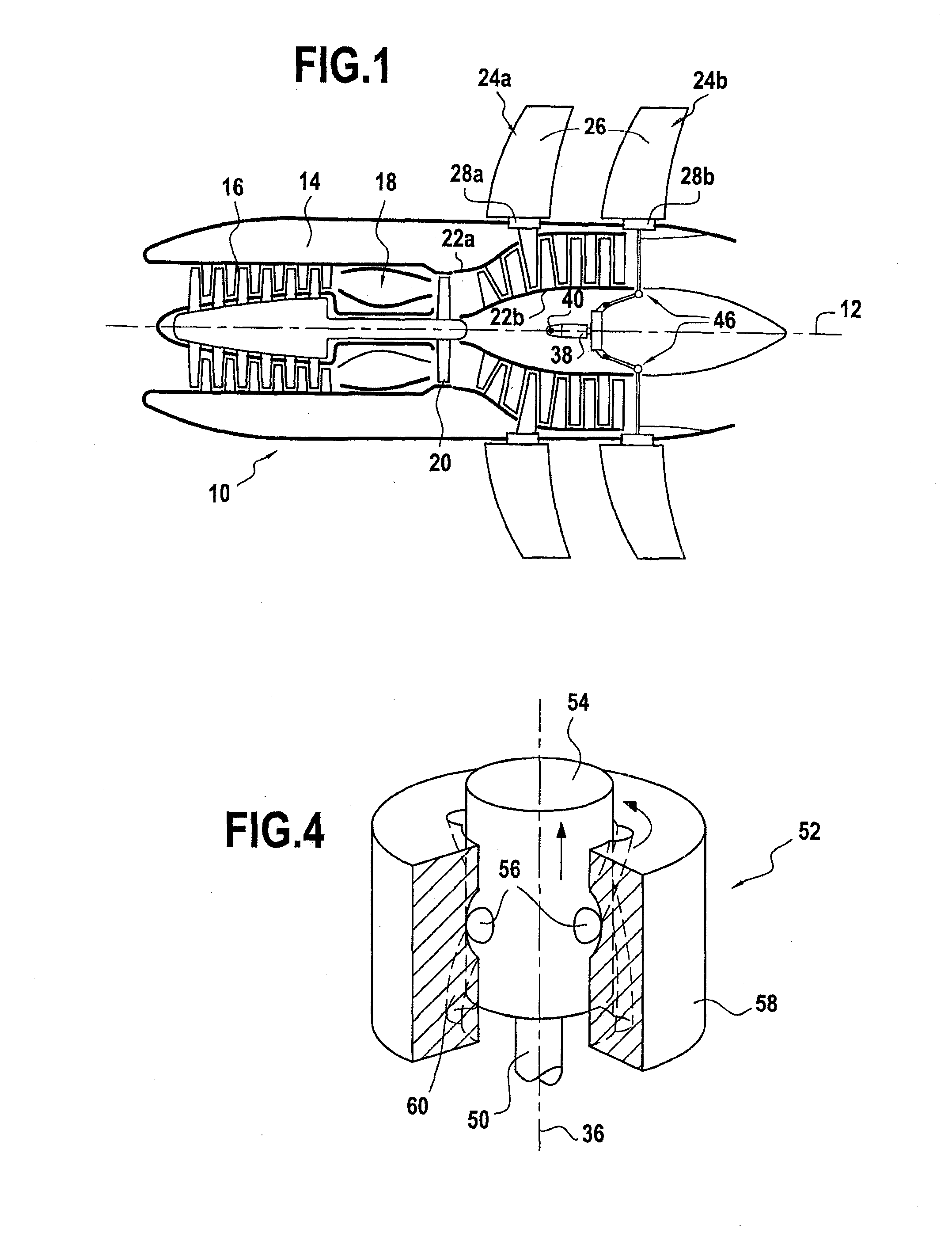
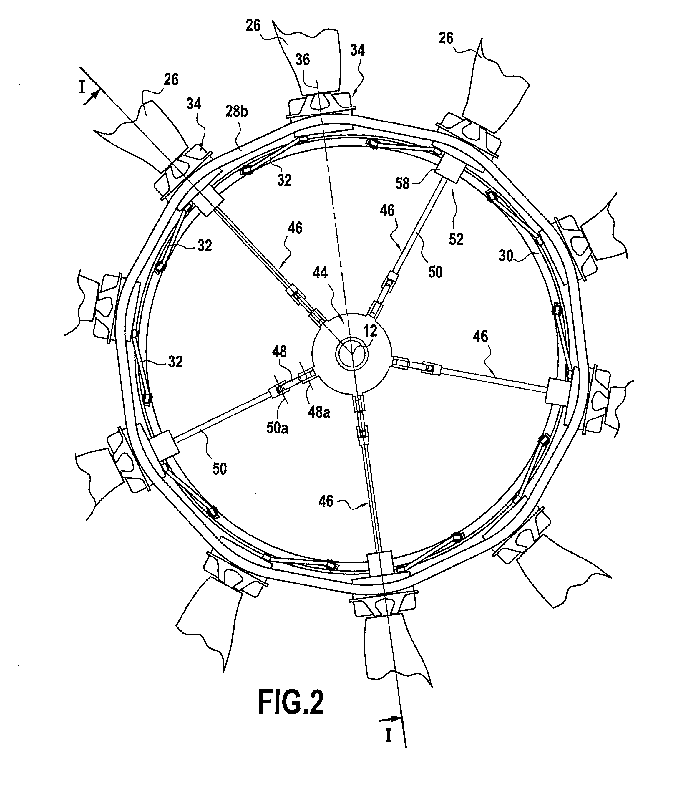
The present invention proposes a device for controlling the pitch of fan blades of a turboprop without requiring hydraulic services to be set into rotation. The device includes a turntable mounted on a stationary structural element of the turboprop, an actuator for moving the turntable, and a synchronization ring connected to the blade set. The actuator is mounted on the stationary structural element, eliminating the harmful effects of centrifugal force. The device also includes a set of connection arms that mechanically connect the synchronization ring to the blade set. The connection arms have a cylindrical outside surface with projecting balls that co-operate with helical fluting in the blade root support. The invention also provides a two-propeller turboprop with variable-pitch fan blades controlled by the device.

Problems solved by technology

The stator portion of the turboprop is remote from this set, such that it is difficult to install actuators that are secured to a structural element that is stationary.
Nevertheless, controlling the pitch of fan blades by means of actuators carried by the rotary portions of the turboprop presents drawbacks.
In particular, feeding hydraulic fluid to actuators that are moving in rotation gives rise to manifest practical problems of implementation.
Furthermore, the behavior of hydraulic fluid when subjected to centrifugal force is not well known and of uncertain reliability.

Method used


Image

  • Stationary actuator device for controlling the pitch of fan blades of a turboprop
  • Stationary actuator device for controlling the pitch of fan blades of a turboprop
  • Stationary actuator device for controlling the pitch of fan blades of a turboprop

Examples


second embodiment

[0038]In the invention as shown in FIG. 5, the conversion means for converting the movement of the radial link 50 of each connection arm 46 into turning of the synchronization ring 30 comprise at least one tangential link 62 having one end fastened to the free end of the radial link 50 of a connection arm via a connection that pivots about a longitudinal axis 62a, the free end of this tangential link is pivotally mounted on the synchronization ring.

[0039]As a result, a radial movement of the radial link50 of the connection arm 46 causes the synchronization ring 30 to turn about the longitudinal axis 12 by means of the tangential link 62. Since the synchronization ring is connected to the blade root support 34 (by means of the drive links 32), turning of the ring changes the pitch of the blades 26 mounted on the supports.

third embodiment

[0040]In the invention as shown in FIG. 6, the conversion means likewise comprise a tangential link 62′ having one end fastened to the free end of the radial link 50 of a connection arm 46 by means of a connection that pivots about a longitudinal axis 62′a, the free end of this tangential link nevertheless being fastened to a blade root support 34 by means of a ball-joint type connection 62′b.

[0041]Thus, a radial movement of the radial link 50 of the connection arm 46 causes the blade root support 34 to swivel about its radial axis 36, and consequently changes the pitch of the blade 26 mounted on said support. Furthermore, since the support 34 is connected to the synchronization ring by means of a drive link 32, swiveling of the support causes the synchronization ring to turn about the longitudinal axis 12.

[0042]It should be observed that these last two embodiments may be combined. The tangential link(s) of one or more connection arms may be connected directly to the synchronizatio...


PUM


Abstract

A device for controlling pitch of fan blades of a turboprop including at least one set of variable-pitch fan blades constrained to rotate with a rotary ring centered on a longitudinal axis and mechanically connected to a turbine rotor, each blade coupled for pitch adjustment to a synchronization ring. A turntable is mounted via a rotary connection to a rod of an actuator that is secured to a stationary structural element of the turboprop, the turntable being mechanically connected to the synchronization ring by a plurality of connection arms hinge-mounted on the turntable and connected to the synchronization ring such that a longitudinal movement of the turntable under drive from the actuator causes the synchronization ring to turn about the longitudinal axis.

Description

BACKGROUND OF THE INVENTION[0001]The present invention relates to the general field of turboprops including at least one set of variable-pitch fan blades. The invention relates more particularly to controlling the pitch of fan blades in a two-propeller airplane turboprop.[0002]In known manner, a two-propeller airplane turboprop comprises a turbine having two contrarotating rotors, each driving a set of unducted fan blades. By way of example, reference may be made to document GB 2 129 502 that describes various embodiments of such a turboprop. The invention applies more particularly to turboprops in which the propellers are mounted at the rear.[0003]In this type of turboprop, the pitch of the fan blades in each set (i.e. the angular orientation of each blade) constitutes a parameter that is used for controlling the thrust of the turboprop. For this purpose, a known solution for controlling the pitch of the fan blades in a given set has recourse to actuators that are positioned on the...

Claims


Application Information

Patent Timeline
Patent Type & Authority Applications(United States)
IPC IPC(8): B64C11/30
CPCB64C11/32B64C11/48F05D2260/79F01D7/00B64D2027/026B64D27/026
Inventor BELMONTE, OLIVIERBOSCO, FRANCK EMMANUEL
Owner SN DETUDE & DE CONSTR DE MOTEURS DAVIATION S N E C M A
Learn More