
Door locking apparatus

Inactive Publication Date: 2012-04-26
U SHIN LTD
View PDF29 Cites 36 Cited by
  • Summary
  • Abstract
  • Description
  • Claims
  • Application Information

AI Technical Summary

Benefits of technology

[0012]In the door locking apparatus with automatic operating specifications, although the automatic locking mechanism is disposed in the second housing that is different from the first housing in which the door opening mechanism is disposed, a rotational driving torque of the automatic locking mechanism can be transmitted to the door opening mechanism through the communication hole of each housing. In the door locking apparatus, the door opening mechanism and the manual locking mechanism are accommodated in the closed first housing, and the automatic locking mechanism is accommodated in the closed second housing. Therefore, a waterproof property and a burglar-proof property can be maintained.
[0013]In the door locking apparatus with manual operating specifications, the door opening mechanism and the manual locking mechanism are disposed in the first housing, so that a driving force of the manual locking mechanism can securely be transmitted to the door opening mechanism. Because necessity to provide a space in which the automatic locking mechanism is accommodated is eliminated in the first housing, the miniaturization and the weight reduction can be implemented. In the door locking apparatus, the door opening mechanism and the manual locking mechanism are accommodated in the closed first housing, so that the waterproof property and the burglar-proof property can be maintained.
[0014]In the door locking apparatus with automatic operating specifications, a switching lever constituting the manual locking mechanism is turnably disposed in the first communication hole of the first housing, an output shaft that outputs the rotational driving torque of the automatic locking mechanism is disposed in the second communication hole of the second housing, the switching lever and the output shaft are coupled through the first and second communication holes so as not to be able to relatively turn, and through the manual locking mechanism, the automatic locking mechanism moves the door opening mechanism to the unlocking position and the locking position. Therefore, the automatic locking mechanism accommodated in the second housing can easily be coupled. Further, the manual locking mechanism is also used to transmit the rotational driving torque of the automatic locking mechanism to the door opening mechanism. Therefore, a configuration of components disposed in the first housing can be simplified.
[0016]Preferably an annular sealing member is disposed between the first and second housings so as to surround the first and second communication holes. Therefore, because water immersion from the communication hole can be prevented, the waterproof property can be ensured.
[0017]In the door locking apparatus with manual operating specifications, a communication hole through which a rotational driving torque of the automatic locking mechanism disposed in the second housing is transmitted to the door opening mechanism is preferably closed in the first housing to which the second housing is not attached. Therefore, the water immersion into the first housing can securely be prevented.
[0018]In the door locking apparatus of the present invention, In a use with the automatic operating specifications, the door opening mechanism and the manual locking mechanism are accommodated in the closed first housing, and the automatic locking mechanism is accommodated in the closed second housing. Therefore, the waterproof property and the burglar-proof property can be maintained. In a use with the manual operating specifications, because the necessity to provide the space in which the automatic locking mechanism is accommodated is eliminated in the first housing, the miniaturization and the weight reduction can be implemented. Additionally, the waterproof property and the burglar-proof property can be maintained.

Problems solved by technology

However, a space in which the automatic locking mechanism is mounted exists in the housing of the door locking apparatus that is used in the manual operating specifications.
Compared with the door locking apparatus that is produced only for the purpose the manual operating specifications, disadvantageously the door locking apparatus has a large housing and uselessly occupies the space.
Disadvantageously, a weight is also increased because of the large housing.

Method used


Image

  • Door locking apparatus
  • Door locking apparatus
  • Door locking apparatus

Examples


Embodiment Construction

[0035]Hereinafter, an embodiment of the invention will be described with reference to the drawings.

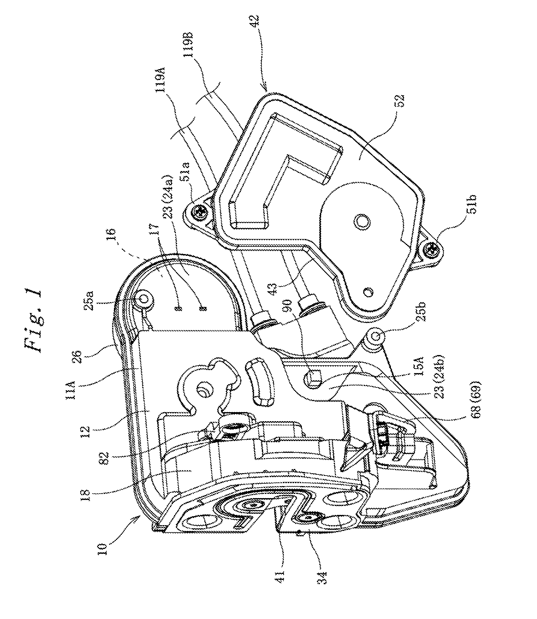
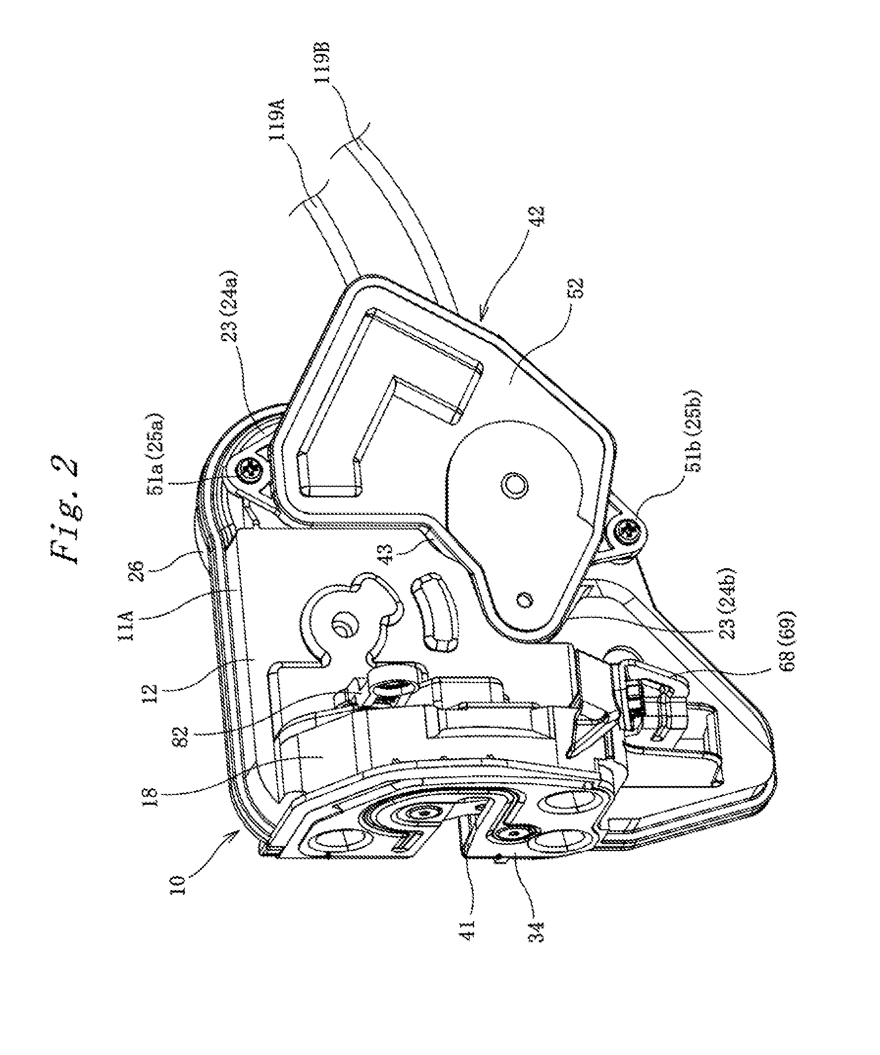
[0036]FIGS. 1 and 2 illustrate a door locking apparatus according to an embodiment of the present invention. The door locking apparatus of the embodiment is mounted on a door of a vehicle, and the door locking apparatus includes a latch mechanism that can latch and release a striker 1 provided on a vehicle body, a door opening mechanism that releases the striker 1 latched by the latch mechanism, and a manual locking mechanism and an automatic locking mechanism, which move the door opening mechanism to an unlocking position or a locking position.

[0037]In the embodiment, the latch mechanism, the door opening mechanism, and the manual locking mechanism are accommodated in a first housing 10, the automatic locking mechanism is accommodated in a second housing 42, and the second housing 42 can optionally be attached to the first housing 10. Therefore, the door locking apparatus is configure...


PUM


Abstract

A door locking apparatus that can be used for both manual operating specifications and automatic operating specifications and that is capable of miniaturization and weight reduction in a use for the manual operating specifications includes a latch mechanism, a door opening mechanism and a manual locking mechanism wherein, a first housing (10) in which the door opening mechanism and the manual locking mechanism are disposed and a second housing (42) in which an automatic locking mechanism that moves the door opening mechanism to the unlocking position or the locking position based on an input of an electric signal is disposed are provided, and a second housing attaching portion (23) to which the second housing (42) can be attached is provided on the first housing (10).

Description

BACKGROUND OF THE INVENTION[0001]1. Field of the Invention[0002]The present invention relates to a door locking apparatus that is mounted on a door of a vehicle.[0003]2. Description of Related Art[0004]This kind of door locking apparatus includes a latch mechanism, and the latch mechanism includes a fork that retains a striker provided on a vehicle side and a claw that engages with the fork to keep the fork latching the striker. The door locking apparatus also includes a door opening mechanism that can switch between an unlocking position where the claw can be engaged and a locking position where the claw cannot be engaged. The door locking apparatus also includes a locking mechanism that moves the door opening mechanism to the unlocking position or the locking position. The locking mechanism includes a manual locking mechanism and an automatic locking mechanism. The manual locking mechanism is operated by a manipulation of a locking knob disposed on the inner side of the vehicle or...

Claims


Application Information

Patent Timeline
IPC IPC(8): E05B65/32E05B83/36B60J5/00E05B77/34E05B79/10E05B81/06E05B81/72E05B85/02
CPCE05B63/0065E05B77/34E05B81/06Y10S292/23E05B81/36E05B85/02E05B81/16Y10T70/5155Y10T292/1047Y10T292/1082
Inventor YAMAGATA, MIKIOAKAGI, NOBUYA
Owner U SHIN LTD
Learn More