Rotating field sensor
- Summary
- Abstract
- Description
- Claims
- Application Information
AI Technical Summary
Benefits of technology
Problems solved by technology
Method used
Image
Examples
first embodiment
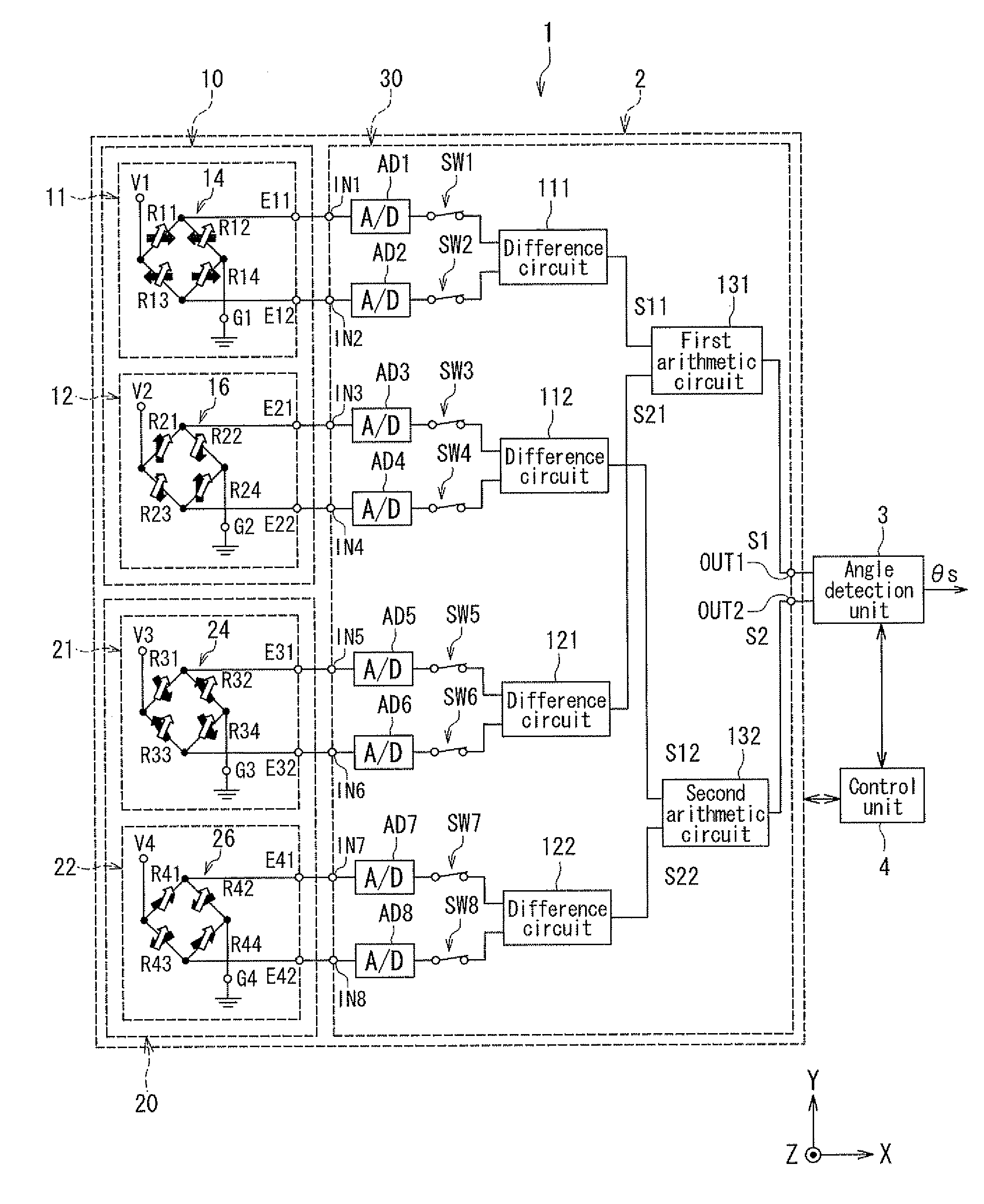
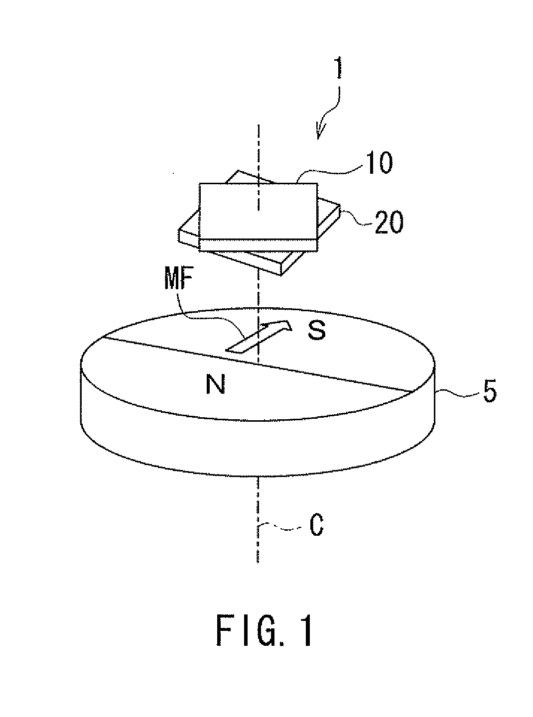
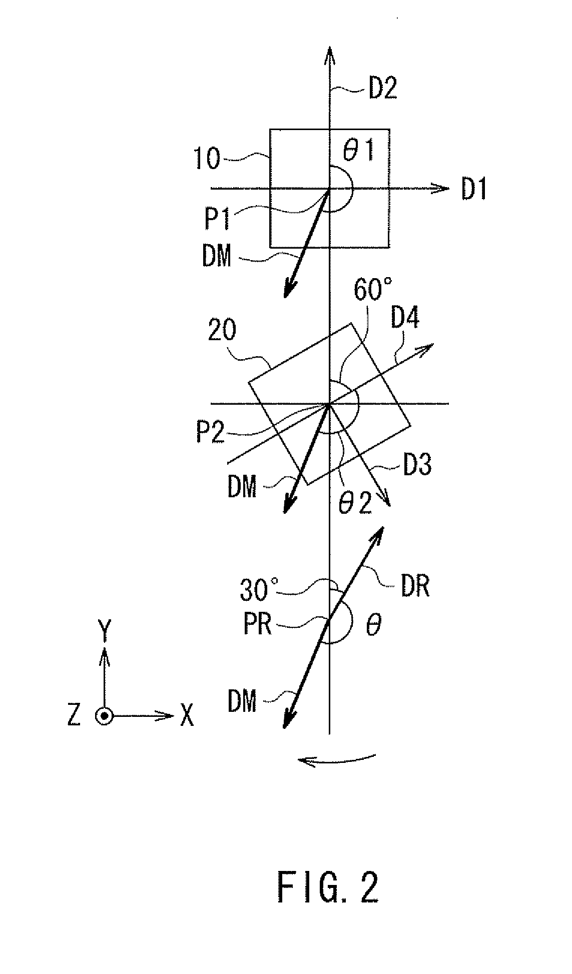
[0060]Preferred embodiments of the present invention will now be described in detail with reference to the drawings. First, reference is made to FIG. 1 and FIG. 2 to describe the general configuration of a rotating field sensor according to a first embodiment of the invention. FIG. 1 is a perspective view showing the general configuration of the rotating field sensor according to the present embodiment. FIG. 2 is an explanatory diagram illustrating the definitions of directions and angles in the present embodiment.
[0061]As shown in FIG. 1, the rotating field sensor 1 according to the present embodiment detects the angle that the direction of a rotating magnetic field MF in a reference position forms with respect to a reference direction. In FIG. 1, a cylindrical magnet 5 is shown as an example of means for generating the rotating magnetic field MF whose direction rotates. The magnet 5 has an N pole and an S pole that are arranged symmetrically with respect to a virtual plane includi...
second embodiment
[0184]A rotating field sensor according to a second embodiment of the invention will now be described with reference to FIG. 23. FIG. 23 is an explanatory diagram showing the configuration of the rotating field sensor according to the present embodiment. In FIG. 23, a magnet 6 including one or more pairs of N and S poles alternately arranged in a ring shape is shown as an example of the means for generating a rotating magnetic field whose direction rotates. In the example shown in FIG. 23, the magnet 6 includes two pairs of N and S poles. The rotating field sensor 1 according to the present embodiment detects the direction of the rotating magnetic field generated from the outer periphery of the magnet 6. In the example shown in FIG. 23, the plane of the drawing of FIG. 23 is an XY plane, and the direction perpendicular to the plane is the Z direction. The N and S poles of the magnet 6 are arranged symmetrically with respect to the center of rotation parallel to the Z direction. The ...
modification examples
[0187]Reference is now made to FIG. 24 to FIG. 26 to describe first to third modification examples of the present embodiment. The first modification example will be described first, with reference to FIG. 24. FIG. 24 is an explanatory diagram showing the configuration of a rotating field sensor of the first modification example of the present embodiment. The configuration of the rotating field sensor 1 of the first modification example is basically the same as that of the rotating field sensor shown in FIG. 23. In the example shown in FIG. 24, the first direction D1 and the third direction D3 differ from each other by 60° in the direction of rotation of the rotating magnetic field, and are both tilted with respect to the radial direction of the magnet 6 in the XY plane. Preferably, the angles that the first direction D1 and the third direction D3 form with respect to the radial direction of the magnet 6 are equal in absolute value, and more specifically, −30° and 30° (the direction ...
PUM
 Abstract
Description
Claims
Application Information
 - R&D
- Intellectual Property
- Life Sciences
- Materials
- Tech Scout
- Unparalleled Data Quality
- Higher Quality Content
- 60% Fewer Hallucinations
Browse by: Latest US Patents, China's latest patents, Technical Efficacy Thesaurus, Application Domain, Technology Topic, Popular Technical Reports.
© 2025 PatSnap. All rights reserved.Legal|Privacy policy|Modern Slavery Act Transparency Statement|Sitemap|About US| Contact US: help@patsnap.com


