
Electricity meter tampering detection

a technology of tampering detection and electric meters, applied in the field of tampering detection of electric meters, can solve the problems of cumbersome detection of this theft form, measurement still does not tell where the current theft occurs, and movement detection does not provide for detection of forms

Active Publication Date: 2012-04-19
NXP BV
View PDF6 Cites 9 Cited by
  • Summary
  • Abstract
  • Description
  • Claims
  • Application Information

AI Technical Summary

Benefits of technology

[0005]Among others, it is an object to provide for a technique that makes it possible to detect theft of electricity even if the electricity meter is not tampered with.
[0008]The time delay of the first reflection due to tampering indicates the distance between the meter and the position of tampering. In an embodiment a distance window is applied to detection of the reflections during tampering detection. In this way false detections due to changes further away from the meter can be eliminated.
[0009]In an embodiment the meter circuit keeps a count of repeated reflection measurements in which deviations have been detected and an alarm is generated only if the count exceeds a threshold. In this way alarms due temporary changes or false alarms can be reduced. A count of detections of repeated reflection measurements performed during a period of predetermined length may be used.
[0010]In an embodiment the meter circuit comprises a transponder for communicating with the electricity company, for example to report electricity use. In a further embodiment messages received via the transponder are used to trigger the detection of reflections. In this way testing in different electricity meters can be coordinated.

Problems solved by technology

Often this is done by connecting power cables to the feed into a house in front of the electricity meter, or by tampering with the operation of the electricity meter itself.
Currently, detection of this form of theft is cumbersome.
However, movement detection does not provide for detection of forms of theft wherein power lines are tapped at some distance from the electricity meter.
But even if all users have accepted more modern electricity meters that can be read off at a distance almost instantaneously, such a measurement still does not tell where the current theft occurs.

Method used


Image

  • Electricity meter tampering detection
  • Electricity meter tampering detection

Examples


Embodiment Construction

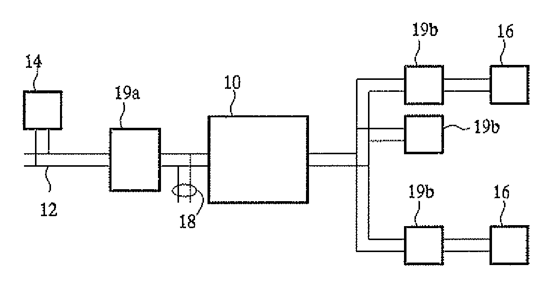
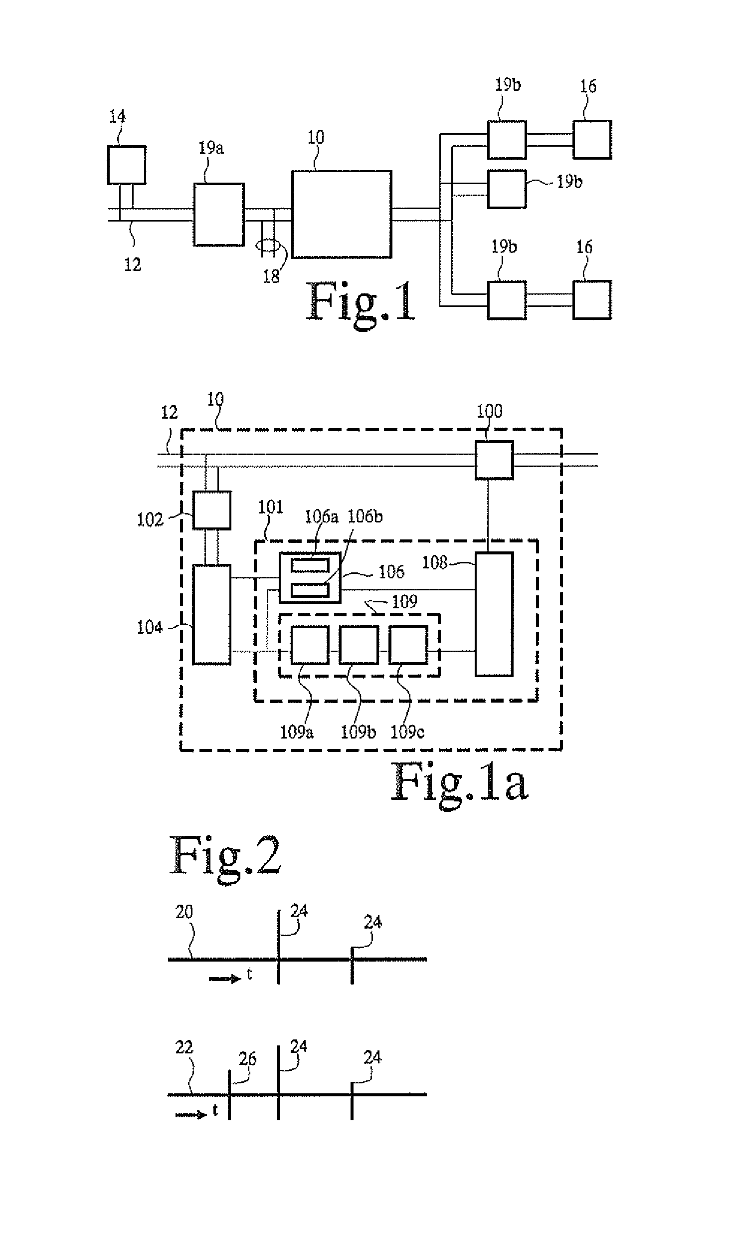
[0016]FIG. 1 shows part of an electricity network. The network comprises an electricity meter 10, a power cable 12 and an information gathering unit 14. Local loads 16 are coupled to power cable 12 via electricity meter 10. In addition an illegal tap 18 coupled to power cable is shown. It should be emphasized that only part of the network is shown. Typically, the network also comprises generators, transformers, circuit breakers etc (not shown). Near electricity meter 10, a master circuit breaker 19a and circuit breakers 19b of various groups of power outlets may be provided.

[0017]FIG. 1a shows electricity meter 10 in more detail. Electricity meter 10 comprises a sensor 100, a meter integrated circuit 101, a transformer 102, and a hybrid 104. Meter integrated circuit 101 comprises a transponder 106, a control circuit 108 and a detector circuit 109. Sensor 100 is coupled between power cable 12 and local loads 16 and sensor 100 has an output coupled to control circuit 108. Control circ...


PUM


Abstract

Tampering with an electricity network is detected from an electricity meter by transmitting a probe signal over at least part of the electricity network (12) from a signal source (106a) in the electricity meter (10). A reflected signal produced by reflection of the probe signal in the electricity network (12) is received back. The reflected signal is compared with a reference signal. An alarm signal is generated when said comparing detects a deviation between the reflection signal and the reference signal, in particular when reflections from a new position on the electricity network near the electricity meter are detected.

Description

FIELD OF THE INVENTION[0001]The invention relates to a method of detecting possible theft of electricity and an detection device for detecting tampering with an electricity network. In an embodiment an electricity meter is provided that is adapted to detect tampering.BACKGROUND OF THE INVENTION[0002]Theft of electricity involves tapping current from the electricity network while avoiding that the current is registered by the electricity meter that is used to bill the user. Often this is done by connecting power cables to the feed into a house in front of the electricity meter, or by tampering with the operation of the electricity meter itself. Currently, detection of this form of theft is cumbersome. Usually it involves visual inspection by a human inspector.[0003]Technical alternatives involve the use of electricity meters that are protected against tampering. U.S. Pat. No. 6,232,886 discloses an electricity meter with a movement detector for example. However, movement detection do...

Claims


Application Information

Patent Timeline
Patent Type & Authority Applications(United States)
IPC IPC(8): G08B21/00
CPCG01R22/066H04B2203/5433H04B3/546G01R22/10
Inventor KUYSTERMANS, MARCO
Owner NXP BV
Learn More