Eureka AIR delivers breakthrough ideas for toughest innovation challenges, trusted by R&D personnel around the world.

System and method for optimizing use of plug-in air conditioners and portable heaters

a technology for portable heaters and air conditioners, applied in the direction of mechanical power/torque control, ratio control, computer control, etc., can solve the problems of difficult to achieve savings, the effective cost of running a window unit to cool a single occupied room is lower, and the mechanical efficiency of windows has the lowest

Active Publication Date: 2012-04-12
ECOFACTOR
View PDF4 Cites 162 Cited by
  • Summary
  • Abstract
  • Description
  • Claims
  • Application Information

AI Technical Summary

Problems solved by technology

Centralized systems tend to be most efficient in terms of cooling per unit of energy consumed, while window units tend to have the lowest mechanical efficiency, although there may be circumstances in which the effective cost of running a window unit to cool a single occupied room is lower than using a high-efficiency central air conditioner to cool the entire house when only the one room is occupied.
In practice, savings often prove harder to achieve, for a variety of reasons.
However, portable heaters and window air conditioners are not generally compatible with thermostats designed for central systems.
Although some newer portable heaters and window air conditioners now include built-in thermostats, and future window air conditioners may have networking capabilities, there are millions of window air conditioners in the world that do not have such controls or communications capabilities.
Neither of these devices is likely to enable fully optimized energy management for a connected portable heater or window air conditioner.
The challenge in using a conventional remote-controlled switch to manage the use of a window-mount air conditioner or space heater is that a critical data input required to optimize comfort and energy use is the temperature of the space being conditioned by the attached air conditioner or heater.
However, making the load control device into a self-contained thermostat requires significant additional complexity (and thus expense), such as a complete user interface, and is also likely to yield unsatisfactory results for several reasons.
Whereas thermostats are normally situated in hallways or interior walls at roughly chest or shoulder level for an average adult, and well away from vents (which could cause the thermostat to shut off the HVAC system prematurely), the location of the electrical outlet nearest the air conditioner is likely to be very high or very low on an exterior wall.
This location will both make programming difficult and distort the temperature readings obtained by the device, since the temperature in a given room is likely to vary by several degrees from floor to ceiling, and be unduly influenced by sunlight, nearby windows, etc., as well as by the attached heater or air conditioner itself.
Although progress in residential HVAC control has been slow, tremendous technological change has come to the tools used for personal communication.
But systems that rely on active management decisions by consumers are likely to yield sub-optimal energy management outcomes—in part because consumers are unlikely to devote the attention and effort required to fully optimize energy use on a daily basis; in part because optimization requires information and insights that are well beyond all but the most sophisticated users.
However, with existing solutions, this approach has serious drawbacks.
Because there is no feedback loop between the load and the controller of the load, there is no way to take into account the conditions in the room or the preferences of the occupants or even to validate that the air conditioner has been shut off.
Thus there is little incentive for the occupants of a given room to suffer significant personal discomfort in order to solve a grid-level problem.
With a simple communicating load controller without a sophisticated feedback mechanism, there is no way for the remote manger to know whether such measures have been taken.

Method used


Image

  • System and method for optimizing use of plug-in air conditioners and portable heaters
  • System and method for optimizing use of plug-in air conditioners and portable heaters
  • System and method for optimizing use of plug-in air conditioners and portable heaters

Examples


Embodiment Construction

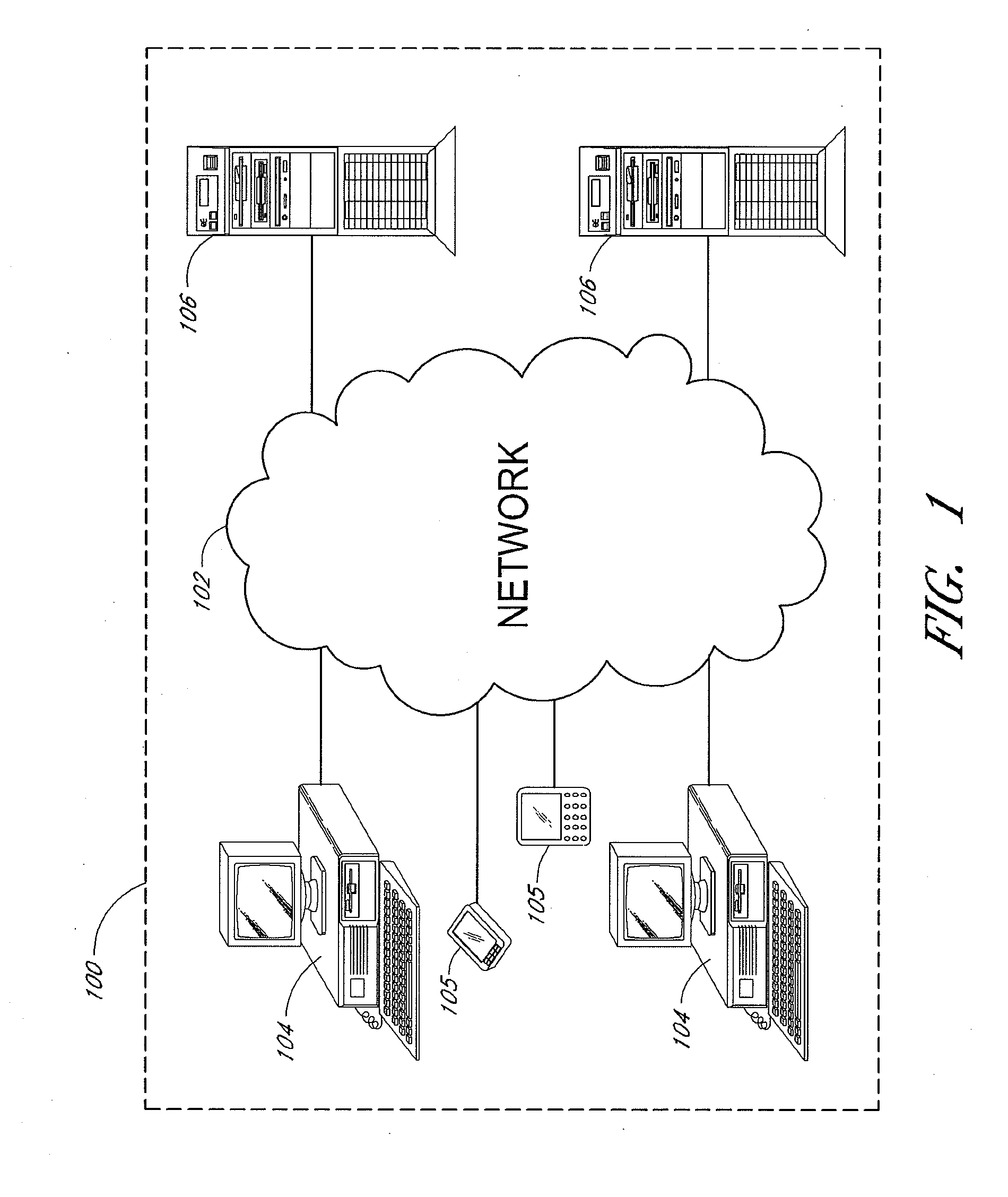
[0079]FIG. 1 shows an example of an overall environment 100 in which an embodiment of the invention may be used. The environment 100 includes an interactive communication network 102 with computers 104 connected thereto. Also connected to network 102 are mobile devices 105, and one or more server computers 106, which store information and make the information available to computers 104 and mobile devices 105. The network 102 allows communication between and among the computers 104, mobile devices 105 and servers 106.

[0080]Presently preferred network 102 comprises a collection of interconnected public and / or private networks that are linked to together by a set of standard protocols to form a distributed network. While network 102 is intended to refer to what is now commonly referred to as the Internet, it is also intended to encompass variations which may be made in the future, including changes additions to existing standard protocols. It also includes various networks used to conn...


PUM


Abstract

Thermostatic HVAC and other energy management controls that are connected to a computer network. For instance, remotely managed load switches incorporating thermostatic controllers inform an energy management system, to provide enhanced efficiency, and to verify demand response with plug-in air conditioners and heaters. At least one load control device at a first location comprises a temperature sensor and a microprocessor. The load control device is configured to connect or disconnect electrical power to the an attached air conditioner or heater, and the microprocessor is configured to communicate over a network. In addition, the load control device is physically separate from an air conditioner or heater but located inside the space conditioned by the air conditioner or heater.

Description

CROSS-REFERENCE TO RELATED APPLICATIONS[0001]This application is a continuation of U.S. patent application Ser. No. 12 / 860,821, filed Aug. 20, 2010, the entirety of which is incorporated herein by reference and are to be considered part of this specification.BACKGROUND[0002]1. Field[0003]The present disclosure relates to the use of thermostatic HVAC and other energy management controls that are connected to a computer network. More specifically, the disclosure relates to the use of remotely managed load switches incorporating thermostatic controllers to inform an energy management system, to provide enhanced efficiency, and to verify demand response with plug-in air conditioners and heaters.[0004]2. Description of the Related Art[0005]Refrigerant-based air conditioning has been on the market for nearly 100 years. Air conditioning systems may be thought of as belonging to one of three broad types: centralized systems, which locate the compressor and condenser outside the conditioned ...

Claims


Application Information

Patent Timeline
Patent Type & Authority Applications(United States)
IPC IPC(8): G05B11/01
CPCG05D23/1923G05D23/19F24F2011/0046F24F11/00G05D23/1905Y02B70/3225Y04S20/222Y04S20/244F24F2110/10F24F2140/50F24F2140/60F24F2120/20F24F11/62F24F11/63F24F11/56F24F11/46F24F11/70F24F11/52F24F11/30H02J2310/14H02J13/00004H02J13/00028H02J3/14Y02B70/30F24F11/58F24F2120/00F24F11/64F24F11/47F24F11/523G05B15/02
Inventor STEINBERG, JOHN DOUGLAS
Owner ECOFACTOR
Why Eureka
Eureka Blog
Learn More