
Device and method for monitoring control channel in multicarrier system

a multi-carrier system and control channel technology, applied in the field of wireless communication, to achieve the effect of reducing the probability of control channel blockag

Active Publication Date: 2012-03-29
LG ELECTRONICS INC
View PDF5 Cites 79 Cited by
  • Summary
  • Abstract
  • Description
  • Claims
  • Application Information

AI Technical Summary

Benefits of technology

The present invention provides a method and apparatus for monitoring a control channel in a multiple carrier system. This is useful for reducing control channel blocking and improving data transmission in wireless communication systems. The invention involves determining a plurality of search spaces for monitoring control channels on a subframe basis and monitoring downlink control channels for successful decoding of control information. The start point of each search space can be determined based on information about the corresponding scheduled component carrier. The invention can be applied to both fixed and mobile user equipments and base stations.

Problems solved by technology

However, it can be inefficient if a multiple carrier system employs the channel structure of a single carrier system as it is.

Method used


Image

  • Device and method for monitoring control channel in multicarrier system
  • Device and method for monitoring control channel in multicarrier system
  • Device and method for monitoring control channel in multicarrier system

Examples


first embodiment

[0136]In a first embodiment, based on the number of CCs allocated for each UE, a start point Yk,i of a i-th UE-specific search space can be defined. If the number of CCs allocated to a UE is N, by using i (i=0, 1, . . . , N-1), a start point Yk,i of the i-th UE-specific search space can be defined as follows.

Yk,i={(A·(Yk-1+i)} mod D or

Yk,i={A·Yk-1+i} mod D  [Equation 3]

[0137]Here, i=0, 1, . . . , N-1; ns is a slot number within a radio frame; k=floor(ns / 2); Yk-1 is a value given from UE ID (e.g., C-RNTI); and A and D parameters can use the values of equation. 2.

[0138]round(x) is a function that rounds off to the nearest integer. ceil(x) is a function that returns the minimum value from integers larger than or equal to x. floor(x) is a function that returns the maximum value from integers smaller than or equal to x.

[0139]Calculating a start point as shown in equation 3 may cause a problem such that UEs with similar UE IEs are made to have the same start point. For example, a first UE...

second embodiment

[0140]In a second embodiment, a start point Yk,j of a j-th UE-specific search space can be defined based on CC index or CIF of a CC allocated for each UE. The start point can be defined as follows.

Yk,j={(A·(Yk-1+j)} mod D or

Yk,j=(A·Yk-1+j)mod D  [Equation 4]

[0141]Here, j denotes at least one of CC index (or CIF) of each DL CC within a UE DL CC set, CC index (or CIF) of all the CCs within a UE DL / UL CC set, and the total number of DL CCs and UL CCs that can be scheduled on a PDCCH monitoring CC. In this case, too, by setting Yk-1=UE ID*Y, a probability that UE-specific search spaces overlap among UEs can be reduced.

third embodiment

[0142]In a third embodiment, based on the number Xq of scheduled CCs that can be scheduled on a PDCCH monitoring CC, a start point Yk,c of a c-th UE-specific search space can be defined. The start point can be defined as follows.

Yk,c={(A·(Yk-1+c)} mod D or

Yk,c=(A·Yk-1+c)mod D  [Equation 5]

[0143]Here, c is CC index of a CC scheduled on a PDCCH monitoring CC, where c=0, 1, . . . , Xq-1. Xq is the number of scheduled CC that can be scheduled on a PDCCH monitoring CC. In this case, too, by setting Yk-1=UE ID*Y, a probability that UE-specific search spaces overlap among UEs can be reduced.

[0144]In the same way, based on CC index cd (cd=0, 1, . . . , Xdq-1) of a scheduled DL CC or CC index cu (cu=0, 1, . . . , Xuq-1) of a scheduled UL CC, a start point of a UE-specific search space for a cd-th or a cu-th CC can be defined.


PUM


Abstract

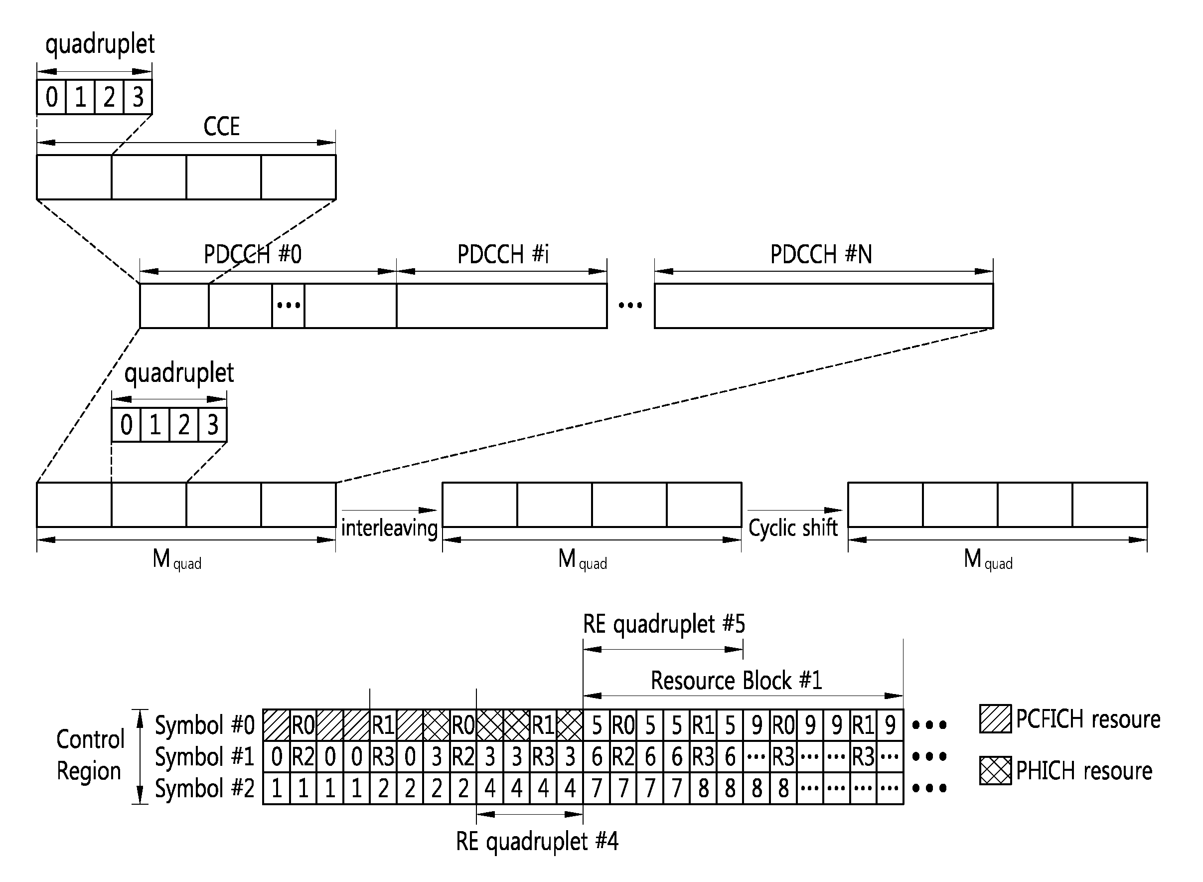
Provided are a method and a device for monitoring the control channel in a multicarrier system. The terminal determines a plurality of terminal-specific search spaces corresponding respectively to a plurality of scheduled component carriers in a control region within a subframe. The terminal monitors a downlink control channel for the scheduled component carriers corresponding respectively to the plurality of terminal-specific search spaces.

Description

TECHNICAL FIELD[0001]The present invention relates to wireless communication. More specifically, the present invention relates to an apparatus and method for monitoring a control channel in a wireless communication system.BACKGROUND ART[0002]Although bandwidth is set differently between uplink and downlink, only one carrier is generally considered in the conventional wireless communication system. The carrier is defined by a center frequency and a bandwidth. A multiple carrier system uses a plurality of component carriers (CCs) having narrow bandwidth than full bandwidth.[0003]A multiple carrier system can support backward compatibility for legacy systems and also increase data rate significantly through multiple carriers.[0004]Long term evolution (LTE) based on 3rd Generation Partnership Project (3GPP) Technical Specification (TS) Release 8 is a promising, next-generation mobile communication standard. A 3GPP LTE system is a single carrier system supporting only one bandwidth (i.e....

Claims


Application Information

Patent Timeline
Patent Type & Authority Applications(United States)
IPC IPC(8): G06F17/30
CPCH04L5/0007H04L5/0035H04L27/2602H04L5/0062H04L5/0053H04L5/001H04L5/0044H04W72/232H04W72/20H04W24/08H04W88/02
Inventor KIM, SO YEONMOON, SUNG HOCHUNG, JAE HOONKWON, YEONG HYEONCHO, HAN GYU
Owner LG ELECTRONICS INC
Learn More