
Earthquake determination system and seismic analysis method

a technology seismic analysis method, which is applied in the field of earthquake determination system or seismic analysis method, can solve the problems of insufficient reliability of earthquake alert, delay in occurrence time, seismic center location, etc., and achieve the effect of high probability

Active Publication Date: 2012-03-29
A2 CO LTD
View PDF1 Cites 20 Cited by
  • Summary
  • Abstract
  • Description
  • Claims
  • Application Information

AI Technical Summary

Benefits of technology

[0035]According to the invention in claims 1 and 3, at an early stage when at least three observation terminal devices detect the earthquake P waves, occurrence of an earthquake can be determined with an extremely high probability.
[0036]Also, even if a large number of the observation terminal devices are arranged in a dispersed manner at random areas, the number of the observation terminal devices which detect the earthquake P waves by the time of determination of occurrence of an earthquake and transmit the estimated P-wave detection information to the seismic analysis processor is several, and no convergence of the communication networks occur, and thus, the estimated P-wave detection information can be obtained by the seismic analysis processor without a delay.
[0037]According to the invention in claim 2, at a stage in which the estimated P-wave detection information is received from at least three observation terminal devices, occurrence of an earthquake can be determined.
[0038]According to the invention in claim 4, the observation terminal device can predict seismic intensity of the earthquake S waves arriving at the installed position with a delay and issues an alert to the periphery without an error.
[0039]Also, the seismic analysis processor can analyze the earthquake occurrence time, seismic center location, and earthquake size at an early stage on the basis of the seismographic information transmitted from the observation terminal device close to the seismic center after determination to be an earthquake.
[0040]Also, since the earthquake wave analysis information is transmitted from the limited number of effective observation terminal devices close to the seismic center, there is no convergence of communication networks and the earthquake wave analysis information consecutively transmitted can be transmitted to the seismic analysis processor without delay.

Problems solved by technology

However, since the vibration detected by the seismographic networks 101 includes living noise such as lightning strike, construction work, traveling of vehicles and the like other than the earthquake waves, it is necessary to determine whether the detected vibration is vibration caused by earthquake P waves or vibration caused by living noise, and since determination requires predetermined time, calculation of the three elements of earthquake (earthquake occurrence time, seismic center location, and earthquake size) is delayed in the end and an alert for a near-field earthquake could not be made in time.
However, in the above-described method in which it is determined to be occurrence of an earthquake if earthquake intensity detected by a seismometer exceeds a set level, even if vibration caused by a living noise exceeds the set level, it is erroneously determined to be an earthquake, and an earthquake alert is not sufficiently reliable.

Method used


Image

  • Earthquake determination system and seismic analysis method
  • Earthquake determination system and seismic analysis method
  • Earthquake determination system and seismic analysis method

Examples


Embodiment Construction

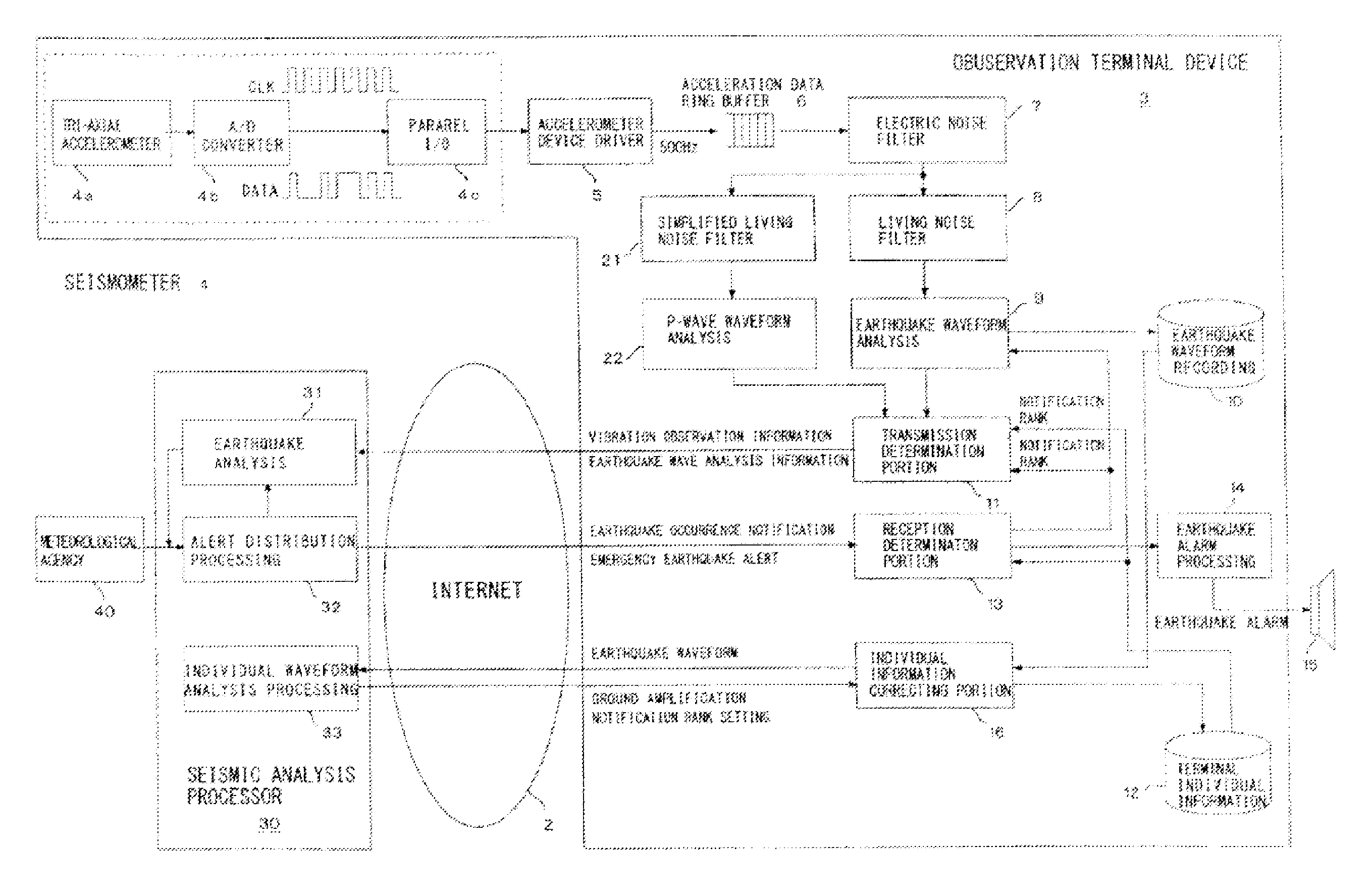
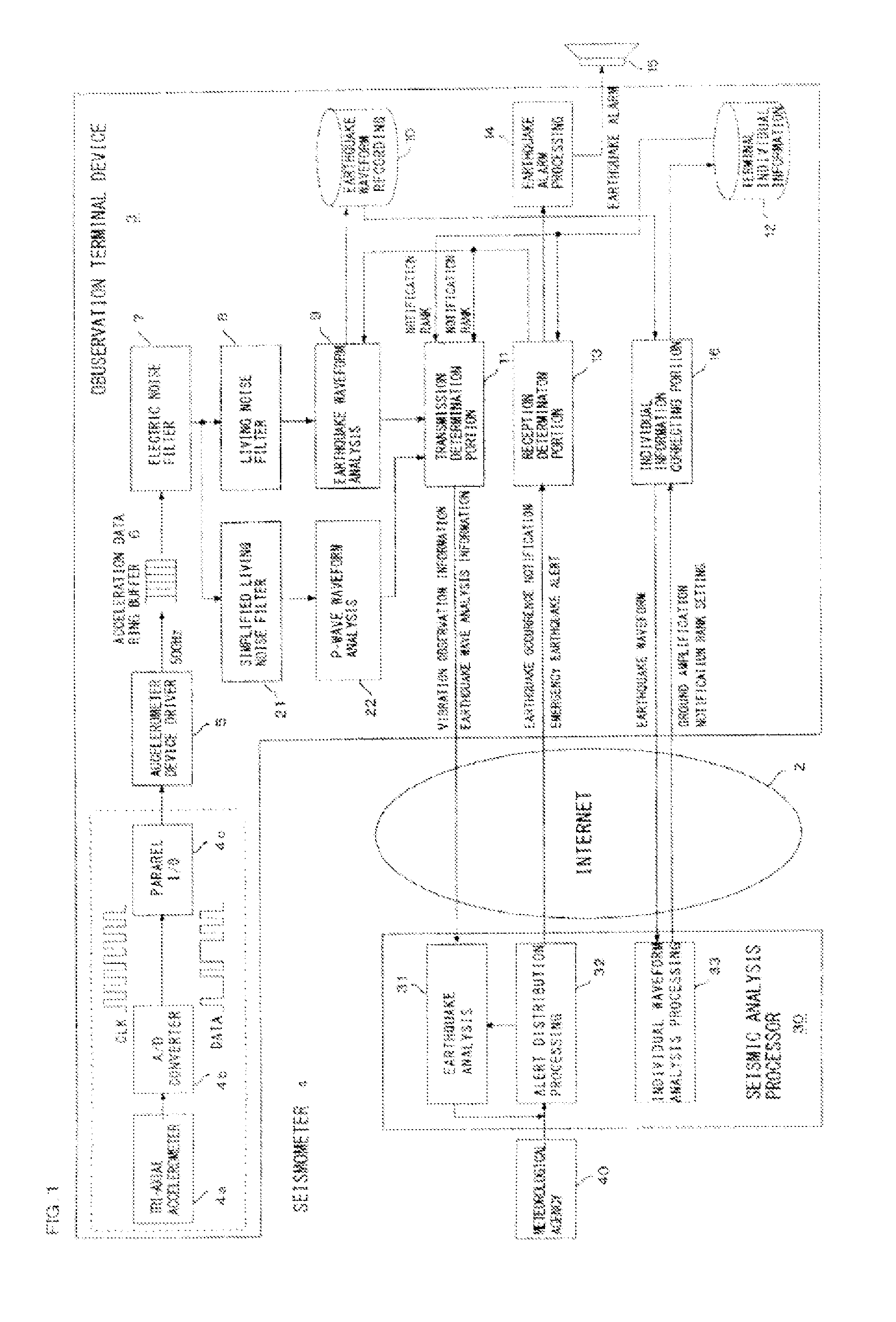
[0050]An earthquake determination system 1 and a seismic analysis method according to an embodiment of the present invention will be described by using FIGS. 1 to 6. FIG. 1 is a block diagram illustrating an entire configuration of the earthquake determination system 1, in which a large number of observation terminal devices 3, 3, . . . installed in a dispersed manner at random areas and a seismic analysis processor 30 are connected through the internet 2, which is a communication network.

[0051]The observation terminal device 3 is installed at a position hardly affected by living noises of a building and at a location where an alarm can be delivered to people living in the building, which will be described later, and incorporates a simplified-type seismometer 4 which detects vibration at the installed position, whereby it functions as an earthquake observation point. The seismometer 4 is formed of a tri-axial accelerometer 4a which detects acceleration caused by vibration at the ins...


PUM


Abstract

An earthquake determination system which includes a plurality of observation terminal devices are connected by a communication network. When estimated P-wave detection information is received from the plurality of the observation terminal devices, a distance D between the observation terminal devices and a time interval δ between detection times are acquired and when transmission limit distance of local vibration energy is DSL, the minimum propagation speed of the earthquake P waves is SP, and the maximum detection error between detection times by the pair of observation terminal devices is Δt, the seismic analysis processor determines occurrence of an earthquake, if the both of the two pairs of the observation terminal devices satisfy the relationships of 2DSL<D and δ<D / SP+Δt.

Description

TECHNICAL FIELD[0001]The present invention relates to an earthquake determination system or a seismic analysis method which determines occurrence of an earthquake at an early stage from vibration at an installed position where an observation terminal device makes observation and more particularly to an earthquake determination system or a seismic analysis method which determines occurrence of an earthquake at an early stage without erroneous determination on the basis of vibration observation information received from a plurality of the observation terminal devices connected to a communication network.BACKGROUND ART[0002]Since it is extremely difficult to predict occurrence of an earthquake, an emergency earthquake alert system is proposed in which earthquake information including earthquake occurrence time, seismic center location and earthquake size is calculated on the basis of earthquake observation information of earthquake P waves observed at a large number of earthquake obser...

Claims


Application Information

Patent Timeline
Patent Type & Authority Applications(United States)
IPC IPC(8): G06F19/00G01V1/30
CPCG01V1/008G01V1/364G01V1/288G01V1/01
Inventor KACHI, MASAAKI
Owner A2 CO LTD
Learn More