
Injection Molding Apparatus and Method of Constructing the Injection Molding Apparatus

a technology of injection molding apparatus and injection molding machine, which is applied in the field of injection molding machine and method of constructing the injection molding machine, can solve the problems of lack of functional improvements and manufacturing versatility, lack of flexibility, and lack of manufacturing versatility in today's marketplace, and achieves the effects of convenient mass production, efficient and economically constructed, and efficient, economical and versatile construction

Inactive Publication Date: 2012-03-29
GALOMB
View PDF3 Cites 0 Cited by
  • Summary
  • Abstract
  • Description
  • Claims
  • Application Information

AI Technical Summary

Benefits of technology

The present invention is a hand-operated injection molding apparatus that is efficient, economical, and versatile. The invention provides a method for constructing the apparatus that facilitates mass production. The apparatus can also be modified with additional functional improvements as desired. Overall, the invention allows for efficient and economical injection molding using a hand-held tool.

Problems solved by technology

Although the early Arburg machines were probably fine machines in their day, their mode of construction wouldn't provide the manufacturing versatility needed in today's globally competitive environment.
What is missing from the prior art machines heretofore is that none are constructed in a way that facilitates an efficient and economical method of mass production.
What is also missing from the prior art machines heretofore is that they lack the functional improvements and manufacturing versatility demanded in today's marketplace.

Method used


Image

  • Injection Molding Apparatus and Method of Constructing the Injection Molding Apparatus
  • Injection Molding Apparatus and Method of Constructing the Injection Molding Apparatus
  • Injection Molding Apparatus and Method of Constructing the Injection Molding Apparatus

Examples


Embodiment Construction

Overview

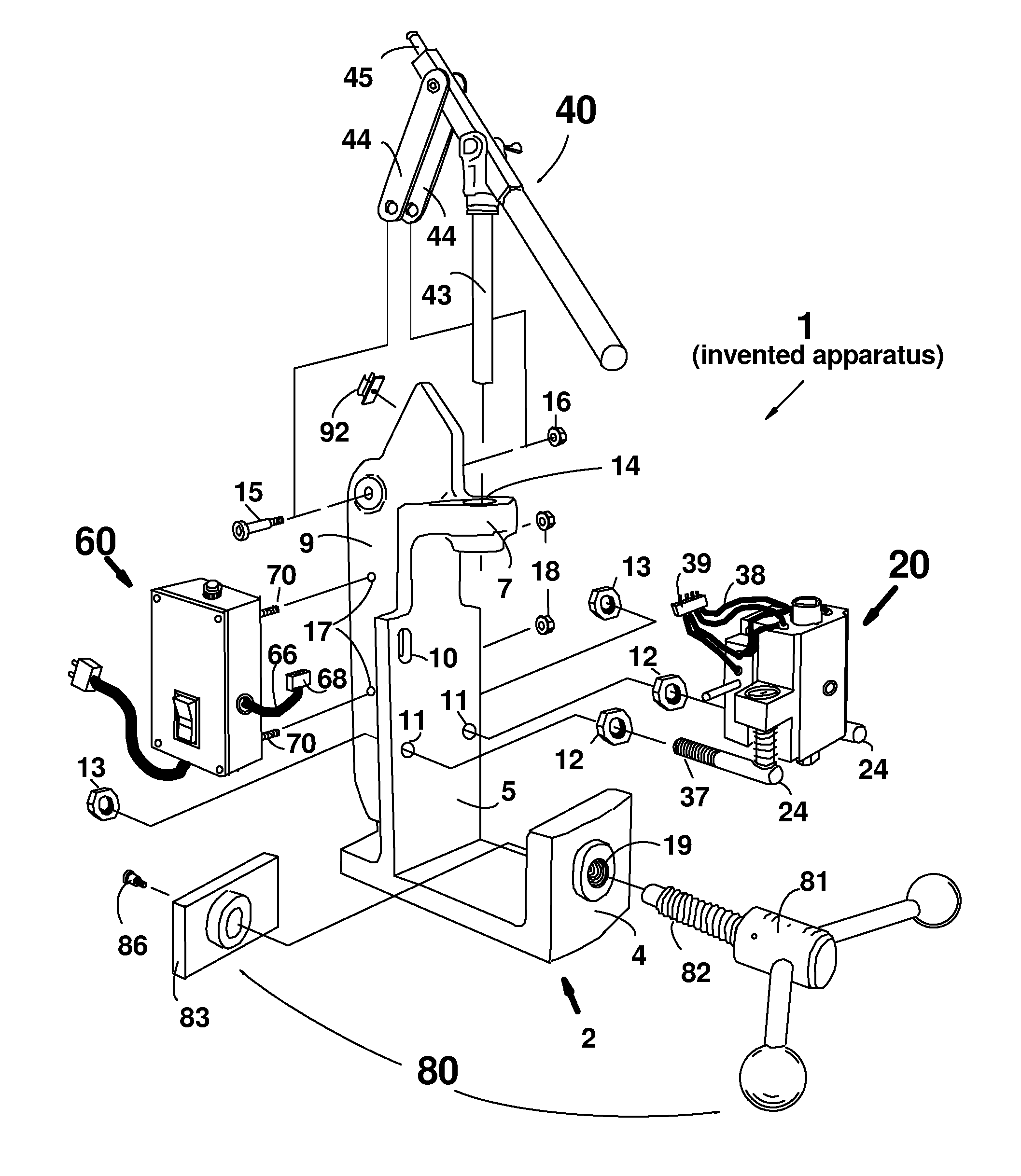
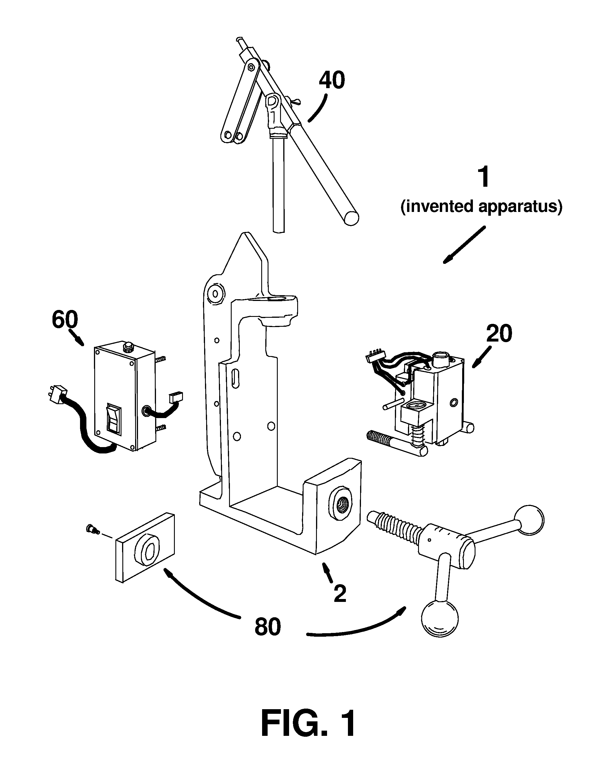
[0024]In the preferred embodiment, and as shown by FIG. 1, the invented apparatus 1 comprises at least; a main support structure, hereafter referred to as the stand 2 for brevity; a heat unit sub-assembly 20; a handle sub-assembly 40; a control box sub-assembly 60; and a mold clamping means 80. The said sub-assemblies 20, 40, 60 and the mold clamping means 80 are each attached to the stand 2 in any desired order, and then the heat unit sub-assembly 20 and the control box sub-assembly 60 are electrically integrated with each other to complete construction of the invented apparatus 1.

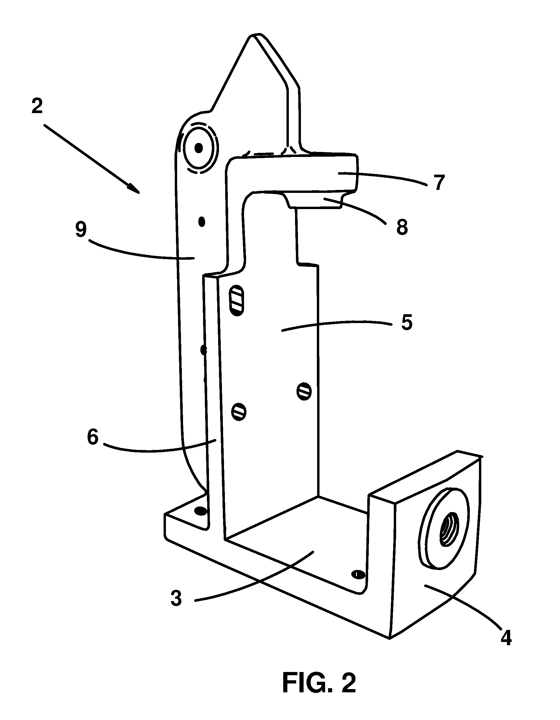
[0025]In the subsequent sections: the stand 2, shown by FIG. 2, will first be described in detail. Then, the heat unit sub-assembly 20, shown by FIG. 3, will be described in detail. Then the handle sub-assembly 40, shown by FIG. 4 will be described in detail. Then the control box sub-assembly 60, shown by FIG. 5 will be described in detail. Then the mold clamping means 80, shown by FIG. 6, will be...


PUM

PropertyMeasurementUnit
temperatureaaaaaaaaaa
electricalaaaaaaaaaa
mass productionaaaaaaaaaa

Abstract

A hand operated injection molding apparatus constructed from prefabricated sub-assemblies and a desired mold clamping means attached to a main support structure, and then electrically integrated with each other

Description

CROSS-REFERENCES TO RELATED APPLICATIONS[0001]This is a continuation-in-part application of the continuation-in-part application U.S. Ser. No. 12 / 390,439 filed on Feb. 21, 2009, which is currently pending and claims the priority of expired provisional application U.S. Ser. No. 61 / 150,863 filed on Feb. 9, 2009 and non-provisional application U.S. Ser. No. 11 / 829,873, now U.S. Pat. No. 7,494,332, filed on Jul. 27, 2007 claiming the priority of expired provisional application U.S. Ser. No. 60 / 834,600 filed on Aug. 1, 2006.BACKGROUND[0002]Hand operated injection molding machines have been around for decades. One of the first machines commercialized was built by Arburg, Inc. in 1954. It was originally designed for internal use to fabricate a particular part. However, in 1956 the company decided to sell the machines outright, ultimately selling over 10,000 units. Although the early Arburg machines were probably fine machines in their day, their mode of construction wouldn't provide the ma...

Claims


Application Information

Patent Timeline
Patent Type & Authority Applications(United States)
IPC IPC(8): B29C47/92B29C48/92
CPCY10T29/49904B29C47/92B29C45/03
Inventor GALOMB, DAVID E.
Owner GALOMB
Learn More