System for Monitoring Electrical Power Usage of a Structure and Method of Same

a technology of electrical power usage and system, applied in the field of electrical power monitoring apparatus, devices, systems, and methods, can solve the problem of difficulty in accurately measuring the magnetic field of one or more main electrical power lines at the surface of electrical circuit breaker panels

Inactive Publication Date: 2012-03-22
BELKIN INT
View PDF17 Cites 26 Cited by
  • Summary
  • Abstract
  • Description
  • Claims
  • Application Information

AI Technical Summary

Problems solved by technology

It is, therefore, difficult to accurately measure the magnetic field of the one o...

Method used


Image

  • System for Monitoring Electrical Power Usage of a Structure and Method of Same
  • System for Monitoring Electrical Power Usage of a Structure and Method of Same
  • System for Monitoring Electrical Power Usage of a Structure and Method of Same

Examples


Embodiment Construction

OF EMBODIMENTS

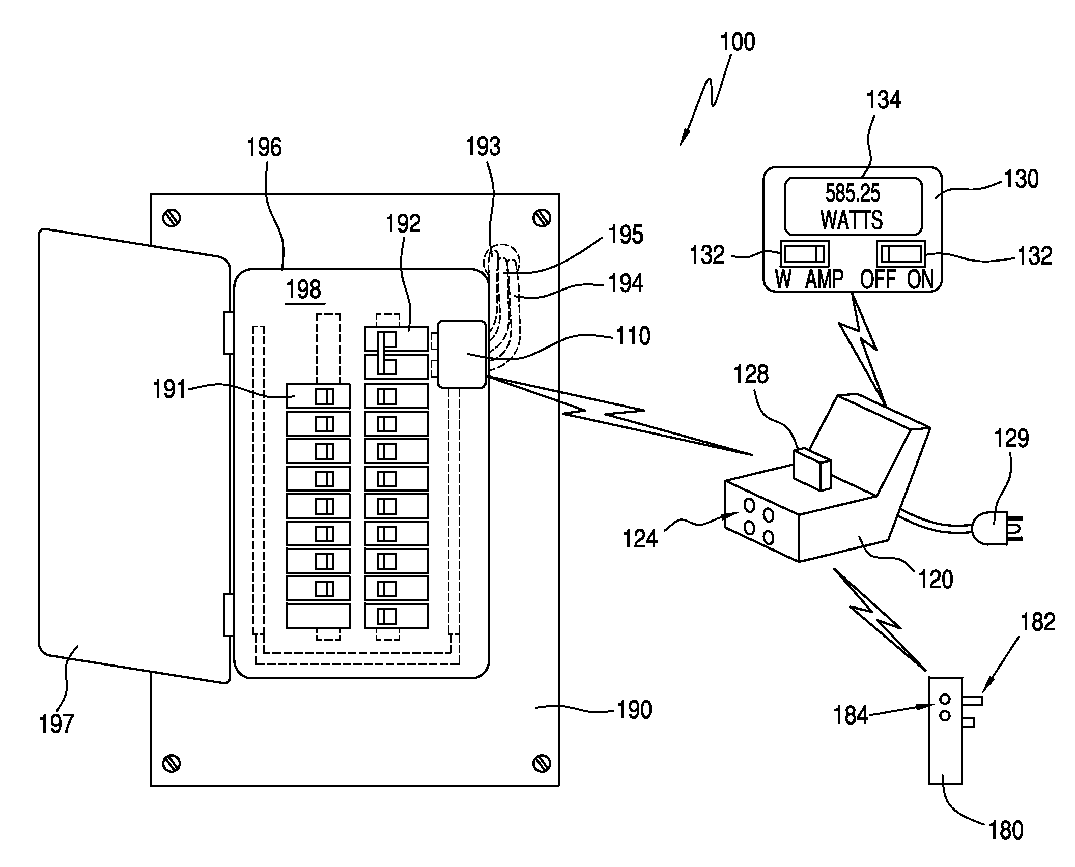
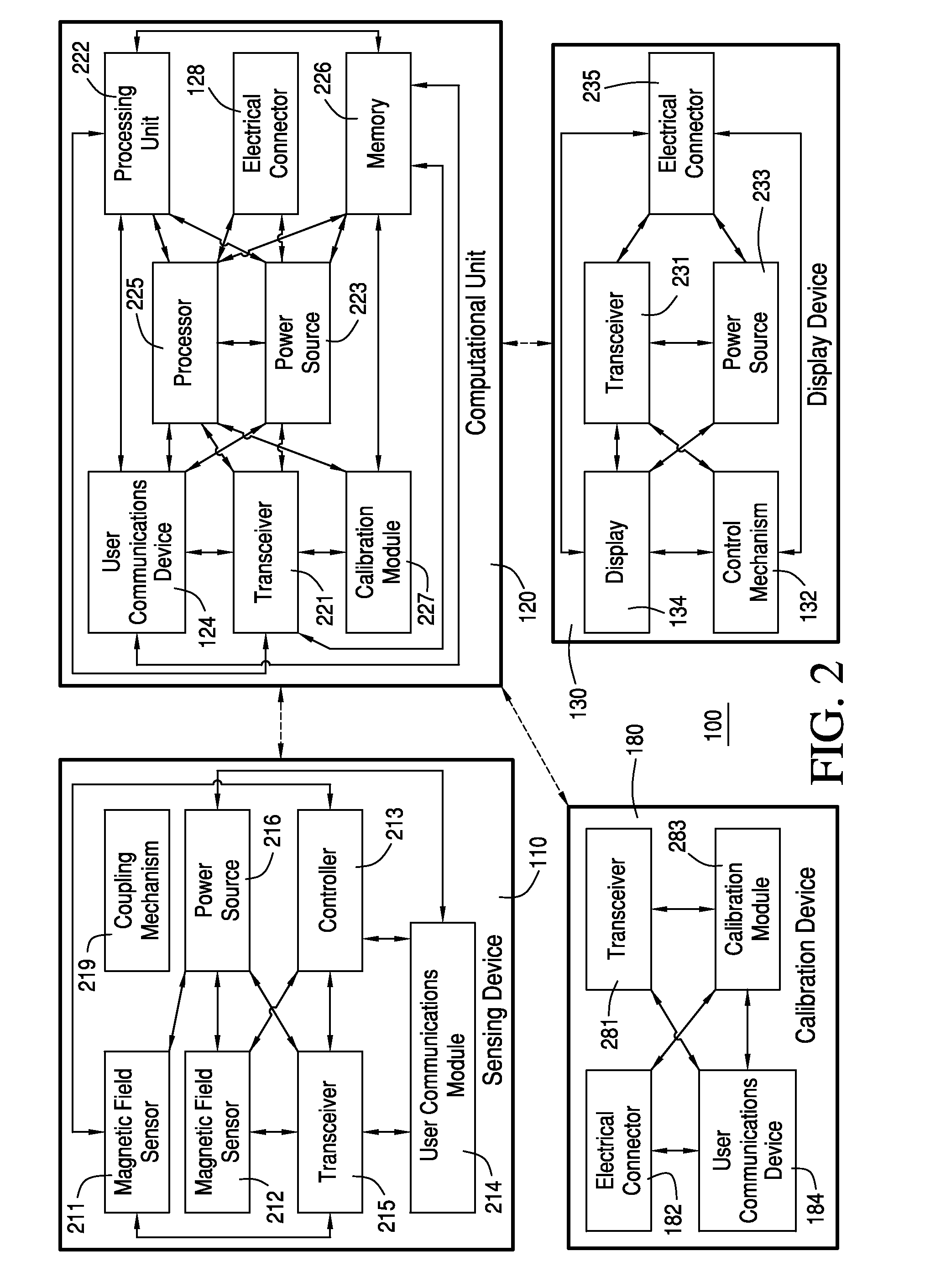
[0036]Some embodiments can teach a system for monitoring usage of electrical power by a structure. The structure can have one or more main electrical power lines that supply the electrical power to a first load in the structure. A portion of the one or more main electrical power lines can run substantially parallel to a first axis. The structure can further have a panel that overlies the portion of the one or more main electrical power lines. The system can include: (a) a current sensor unit configured to be coupled to a portion of a surface of the panel, the current sensor unit having: (a) at least one magnetic field sensor having a length substantially parallel to a second axis, wherein the second axis is substantially perpendicular to the first axis, and the at least one magnetic field sensor is configured to detect a magnetic field generated by the one or more main electrical power lines; and (b) a processing unit configured to run on a processor. The current senso...


PUM


Abstract

Some embodiments can teach a system for monitoring usage of electrical power by a structure. The structure can have one or more main electrical power lines that supply the electrical power to a first load in the structure. A portion of the one or more main electrical power lines can run substantially parallel to a first axis. The structure can further have a panel that overlies the portion of the one or more main electrical power lines. The system can include: (a) a current sensor unit configured to be coupled to a portion of a surface of the panel, the current sensor unit having: (a) at least one magnetic field sensor having a length substantially parallel to a second axis, wherein the second axis is substantially perpendicular to the first axis, and the at least one magnetic field sensor is configured to detect a magnetic field generated by the one or more main electrical power lines; and (b) a processing unit configured to run on a processor. The current sensor unit can be configured to produce an output signal based on the magnetic field detected by the at least one magnetic field sensor. The processing unit further can be configured to receive the output signal from the current sensor unit and process the output signal to determine one or more parameters related to the usage of the electrical power by the first load in the structure. Other embodiments are disclosed.

Description

CROSS-REFERENCE TO RELATED APPLICATIONS[0001]This application claims the benefit of U.S. Provisional Application No. 61 / 361,296, filed Jul. 2, 2010 and U.S. Provisional Application No. 61 / 380,174 filed Sep. 3, 2010. U.S. Provisional Application Nos. 61 / 361,296 and 61 / 380,174 are incorporated herein by reference.FIELD OF THE INVENTION[0002]This invention relates generally to apparatuses, devices, systems, and methods for monitoring electrical power, and relates more particularly to such apparatuses, devices, systems, and methods that monitor electrical power in one or more main electrical power lines at an electrical circuit breaker panel of a structure.DESCRIPTION OF THE BACKGROUND[0003]A structure can have one or more main electrical power lines that supply the electrical power to electrical devices (i.e., the load) in the structure. The main electrical power lines enter the structure through an electrical circuit breaker panel. An electrical circuit breaker panel is the main elect...

Claims


Application Information

Patent Timeline
IPC IPC(8): G06F19/00G01R35/00G01R21/133
CPCG01R15/207G01R21/001G01R21/06G01R22/06G01R22/063G01R33/09G01R35/04G01R15/202G01R35/007G01R31/327G01R33/07G01R35/005G01R21/08G01R33/0035G01R11/32G01R19/00G01R1/20G01R19/0092
Inventor YOGEESWARAN, KARTHIKKELLY, FRANCIS M.PATEL, SHWETAK N.GUPTA, SIDHANTREYNOLDS, MATTHEW S.
Owner BELKIN INT
Why Eureka
Try Eureka