Piezoelectric acoustic transducer
a technology of acoustic transducers and piezoelectrics, applied in piezoelectric/electrostrictive transducers, diaphragm construction, transducer types, etc., can solve problems such as inferior bass reproduction ability, and achieve the effect of high sound pressur
- Summary
- Abstract
- Description
- Claims
- Application Information
AI Technical Summary
Benefits of technology
Problems solved by technology
Method used
Image


Examples
embodiment 1
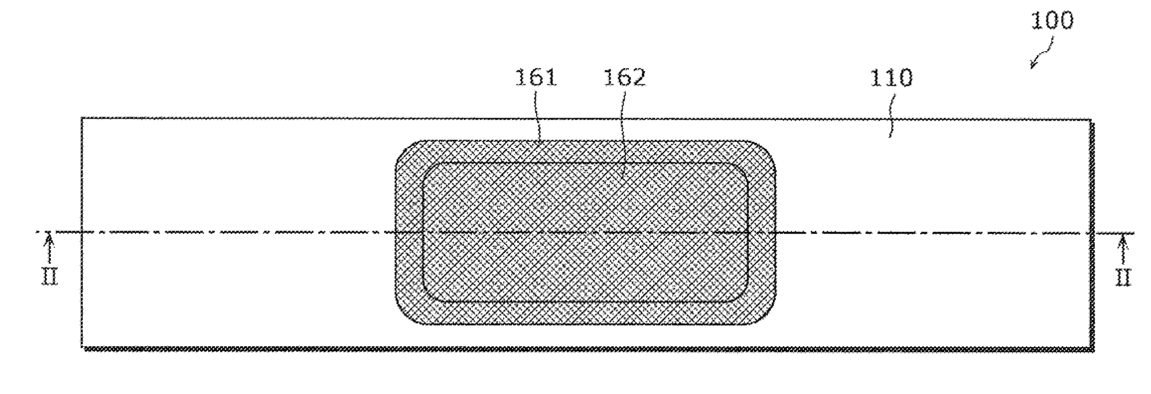
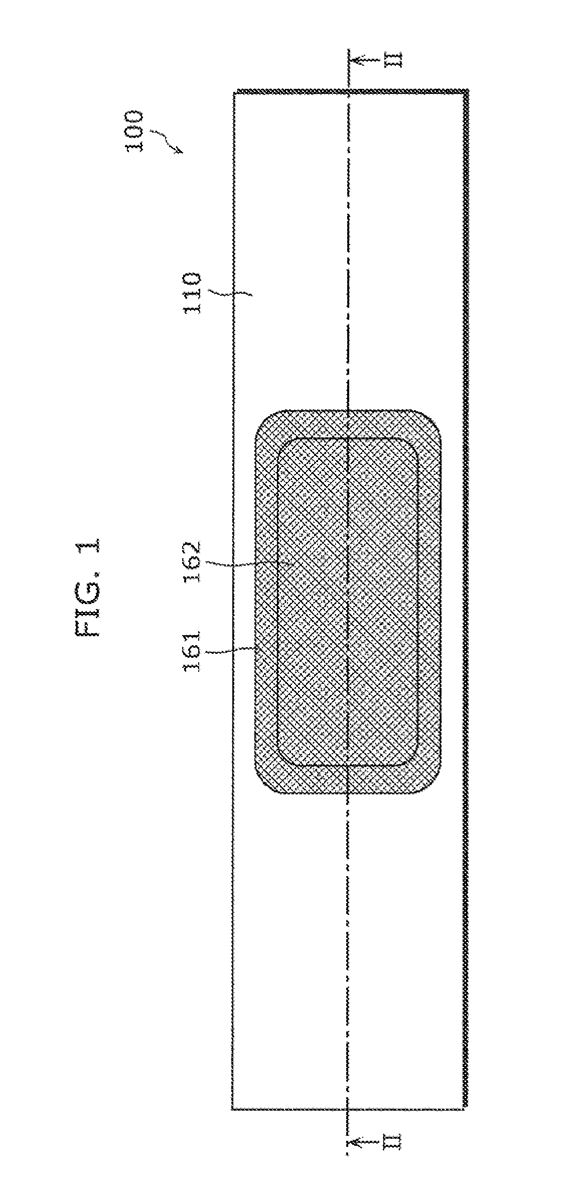
[0053]A piezoelectric speaker 100 according to a first embodiment is described with reference to FIGS. 1 to 6. FIG. 1 is a front view of the piezoelectric speaker 100 according to the first embodiment. FIG. 2 is a cross-sectional view of a section taken along II-II in FIG. 1. FIG. 3 is a cross-sectional view of a section taken along III-III in FIG. 2. FIG. 4 is a cross-sectional view of a section taken along IV-IV in FIG. 2. FIG. 5 is an enlarged view of a first piezoelectric diaphragm 120. FIG. 6 is an enlarged view of a region VI in FIG. 2.
[0054]The piezoelectric speaker 100 according to the first embodiment, as shown in FIGS. 1 to 4, mainly includes: a chassis 110, a first piezoelectric diaphragm 120, second piezoelectric diaphragms 130a and 130b, joint members 140a and 140b, fixing members 150a and 150b, an edge 161, and a radiation plate protection film 162. This piezoelectric speaker 100 is bilaterally symmetric with respect to a center line (not shown) in FIG. 2.
[0055]The cha...
embodiment 2
[0090]A piezoelectric speaker 200 according to a second embodiment is described with reference to FIGS. 11 to 14. FIG. 11 is a plan view of the piezoelectric speaker 200 according to the second embodiment. FIG. 12 is a cross-sectional view of a section taken along XII-XII in FIG. 11. FIG. 13 is a cross-sectional view of a section taken along XIII-XIII in FIG. 12. FIG. 14 is a cross-sectional view of a section taken along XIV-XIV in FIG. 13.
[0091]The piezoelectric speaker 200, as shown in FIGS. 11 to 14, mainly includes: a chassis 210, a first piezoelectric diaphragm 120, second piezoelectric diaphragms 130a and 130b , joint members 140a and 140b, fixing members 250a and 250b, an edge 161, a radiation plate protection film 162, and filling materials 270a and 270b.
[0092]The piezoelectric speaker 200 according to the second embodiment is different from the piezoelectric speaker 100 according to the first embodiment in that the fixing members 250a and 250b in the piezoelectric speaker ...
embodiment 3
[0096]A piezoelectric speaker 300 according to a third embodiment is described with reference to FIGS. 15 to 17. FIG. 15 is a front view of the piezoelectric speaker 300 according to the third embodiment. FIG. 16A is a cross-sectional view of a section taken along XVI-XVI in FIG. 15. FIG. 16B is a diagram showing another form of the connection member. FIG. 17 is a cross-sectional view of a section taken along XVI-XVI in FIG. 16A.
[0097]The piezoelectric speaker 300, as shown in FIGS. 15 to 17, mainly includes: a chassis 110, a first piezoelectric diaphragm 120, second piezoelectric diaphragms 130a and 130b , joint members 140a and 140b, fixing members 150a and 150b, an edge 161, a radiation plate protection film 162, a diaphragm 370, and a connection member 371.
[0098]The piezoelectric speaker 300 according to the third embodiment is different from the piezoelectric speaker 100 according to the first embodiment in that: in the piezoelectric speaker 300, the diaphragm 370 having a coni...
PUM
 Abstract
Description
Claims
Application Information
 - R&D
- Intellectual Property
- Life Sciences
- Materials
- Tech Scout
- Unparalleled Data Quality
- Higher Quality Content
- 60% Fewer Hallucinations
Browse by: Latest US Patents, China's latest patents, Technical Efficacy Thesaurus, Application Domain, Technology Topic, Popular Technical Reports.
© 2025 PatSnap. All rights reserved.Legal|Privacy policy|Modern Slavery Act Transparency Statement|Sitemap|About US| Contact US: help@patsnap.com