
Rotation input device

a technology of input device and rotation input, which is applied in the direction of mechanical control device, pulse technique, instruments, etc., can solve the problems of inability to release electromagnetic brakes and difficulty in determining the direction in which the operation knob is to be rotated, and achieve the effect of accurate setting, simple configuration and easy adjustmen

Active Publication Date: 2012-03-08
ALPS ALPINE CO LTD
View PDF8 Cites 19 Cited by
  • Summary
  • Abstract
  • Description
  • Claims
  • Application Information

AI Technical Summary

Benefits of technology

[0015]In such an embodiment, the rotation input device may further include a third rotary member configured to rotate concentrically with and in unison with the first rotary member. The outer teeth row may be provided for the third rotary member. The second rotary member and the third rotary member may be arranged on the same plane. With this arrangement, the profile of the device in a direction along the axis of rotation of the device can be lowered.
[0017]With this arrangement, properly setting the size of each of the cam member and the driving member allows the angle range of the rotary operation member which is permitted to rotate under condition that the second rotary member is prevented from rotating, namely, play to be set small, thus improving operation feeling.
[0019]In these embodiments, the profile of the device in the direction along the axis of rotation of the device can be further lowered.
[0021]Furthermore, the angle range of play can be accurately set with a simple configuration, thus improving the operation feeling.
[0022]In these embodiments, the other one of the second rotary member and the third rotary member may include protruding portions protruding around the driving member such that the protruding portions are locked by the restricting walls. With this arrangement, if a large force is applied to the rotary operation member prevented from rotating, the rotation of the rotary operation member can be reliably prevented without causing damage on components. Thus, the device offers high reliability.
[0023]The braking unit may include an armature configured to rotate in unison with the second rotary member and be displaceable in the axial direction of the device and a solenoid unit configured to attract the armature in the axial direction. With this arrangement, the rotation of the second rotary member can be stably prevented. Thus, the device offers higher reliability.

Problems solved by technology

If the operation knob is completely locked, it is difficult to determine a direction in which the operation knob is to be rotated.
Disadvantageously, the electromagnetic brake cannot be released.
Unfortunately, the drive shaft is continuously prevented from rotating by the electromagnetic brake and the locked operation knob is not unlocked.

Method used


Image

  • Rotation input device
  • Rotation input device
  • Rotation input device

Examples


Embodiment Construction

[0033]The following description is intended to convey a thorough understanding of the embodiments described by providing a number of specific embodiments and details involving a rotation input device. It should be appreciated, however, that the present invention is not limited to these specific embodiments and details, which are exemplary only. It is further understood that one possessing ordinary skill in the art, in light of known systems and methods, would appreciate the use of the invention for its intended purposes and benefits in any number of alternative embodiments, depending on specific design and other needs.

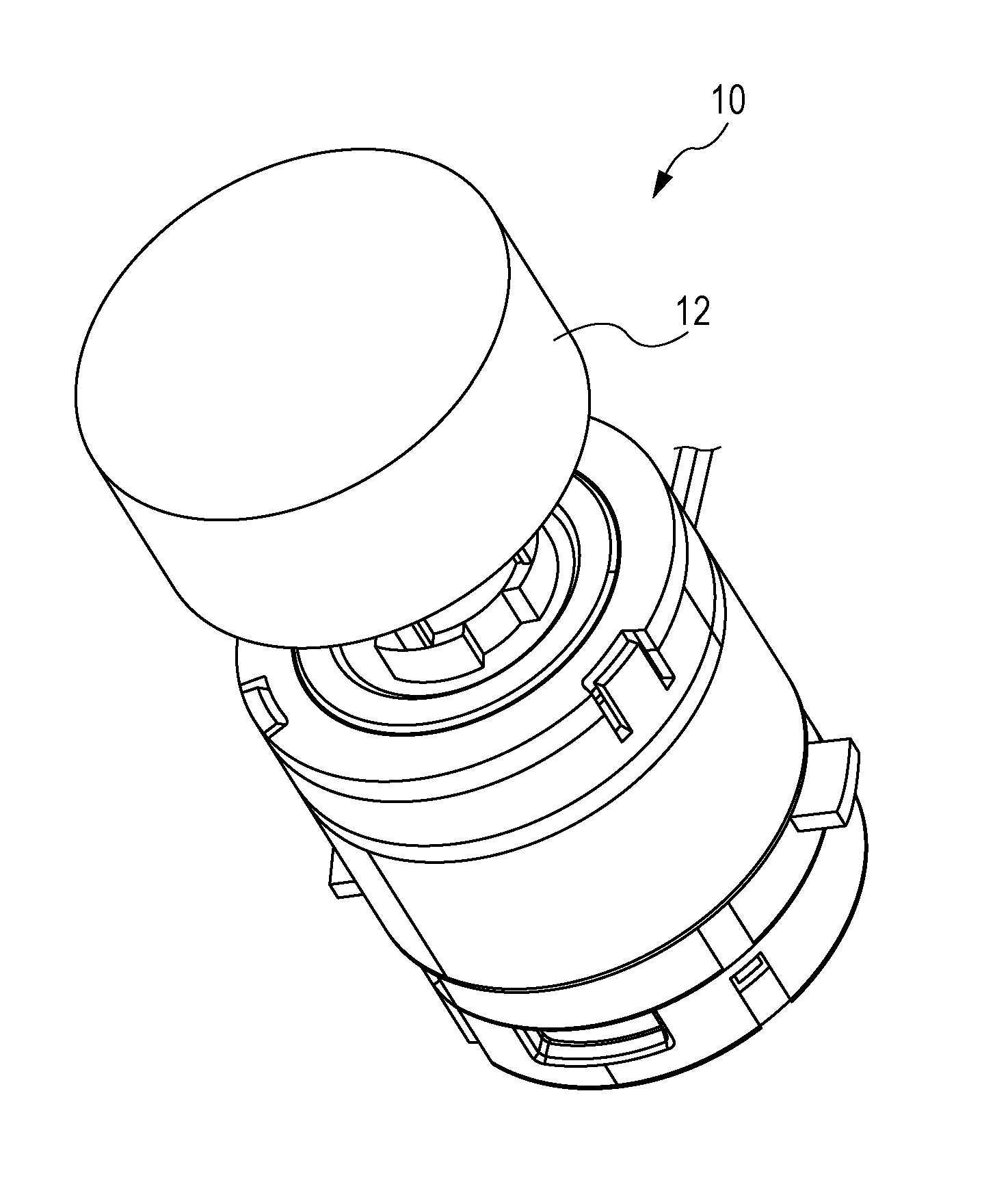
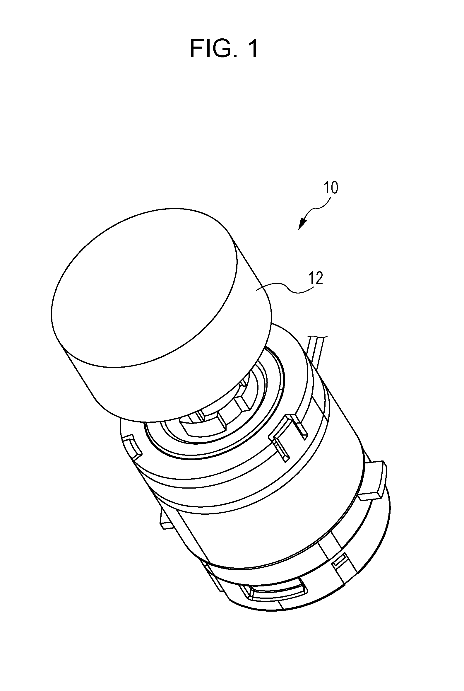
[0034]FIG. 1 is a schematic perspective view of a rotation input device 10 according to an exemplary embodiment of the disclosure. The rotation input device 10 may be used as an input device of, for example, a car air conditioning system and may be installed on an instrument panel or a center console in a vehicle interior.

[0035]The rotation input device 10 may include ...


PUM


Abstract

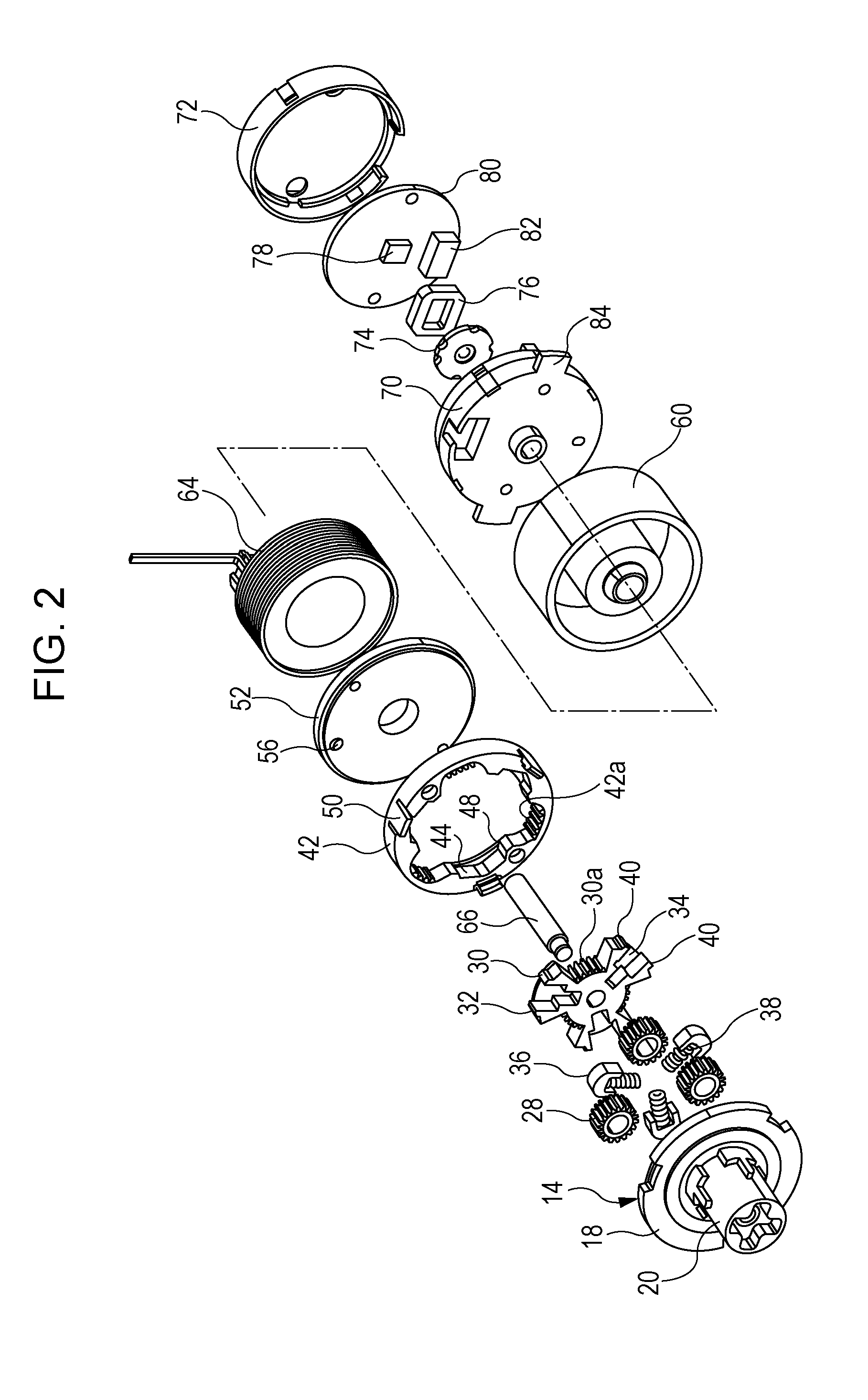
In a rotation input device, a planetary carrier, connected to an operation knob, rotatably supports a planetary gear which meshes with an outer teeth row provided for a sun gear, to which an output shaft is secured, and also meshes with an inner teeth row provided for an outer gear. A plunger provided for the sun gear is in elastic contact with a recess cam provided for the outer gear. A solenoid unit prevents rotation of the outer gear in accordance with an output of a magnetic sensor which faces a magnet provided for the output shaft.

Description

CLAIM OF PRIORITY[0001]This application claims benefit of Japanese Patent Application No. 2010-199749 filed on Sep. 7, 2010, the entire contents of which is hereby incorporated by reference.BACKGROUND OF THE DISCLOSURE[0002]1. Field of the Disclosure[0003]The present disclosure relates to a rotation input device.[0004]2. Description of the Related Art[0005]Input devices included in in-vehicle apparatuses, such as a car navigation system, a car audio system, and a car air conditioning system, include rotation input devices each including an operation knob that is rotated about a single shaft. An operator rotates the operation knob, thereby inputting a proper instruction to such an in-vehicle apparatus.[0006]In some rotation input devices, when the operator rotates the operation knob, an electromagnetic brake applies a braking force to the operation knob in accordance with a rotation position of the operation knob, thus allowing the operator to recognize an operation range and operati...

Claims


Application Information

Patent Timeline
Patent Type & Authority Applications(United States)
IPC IPC(8): H03K17/94
CPCG05G1/08Y10T70/7034Y10T70/7045Y10T70/7085
Inventor SANO, TADASHI
Owner ALPS ALPINE CO LTD
Learn More