Squeegee module

Inactive Publication Date: 2012-03-01
SAMSUNG ELECTRO MECHANICS CO LTD
View PDF4 Cites 0 Cited by
  • Summary
  • Abstract
  • Description
  • Claims
  • Application Information

AI Technical Summary

Benefits of technology

[0011]The present invention has been made keeping in mind the above problems occurring in the related art, and the present invention is intended to provide a squeegee module, in which the moving direction of the squeegee can be easily changed and the inclination angle of the squeegee can be easily controlled in relation to variations in the amount of solder paste, thus maintaining the desired rolled shape of the solder paste and continuously maintaining the viscosity of the solder paste for a lengthy period of time during solder paste printing.
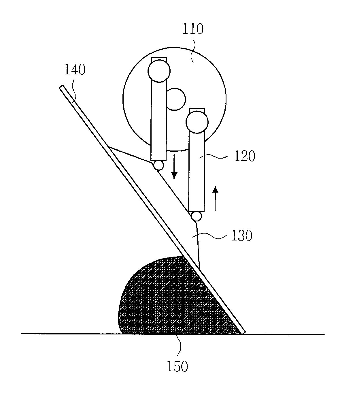
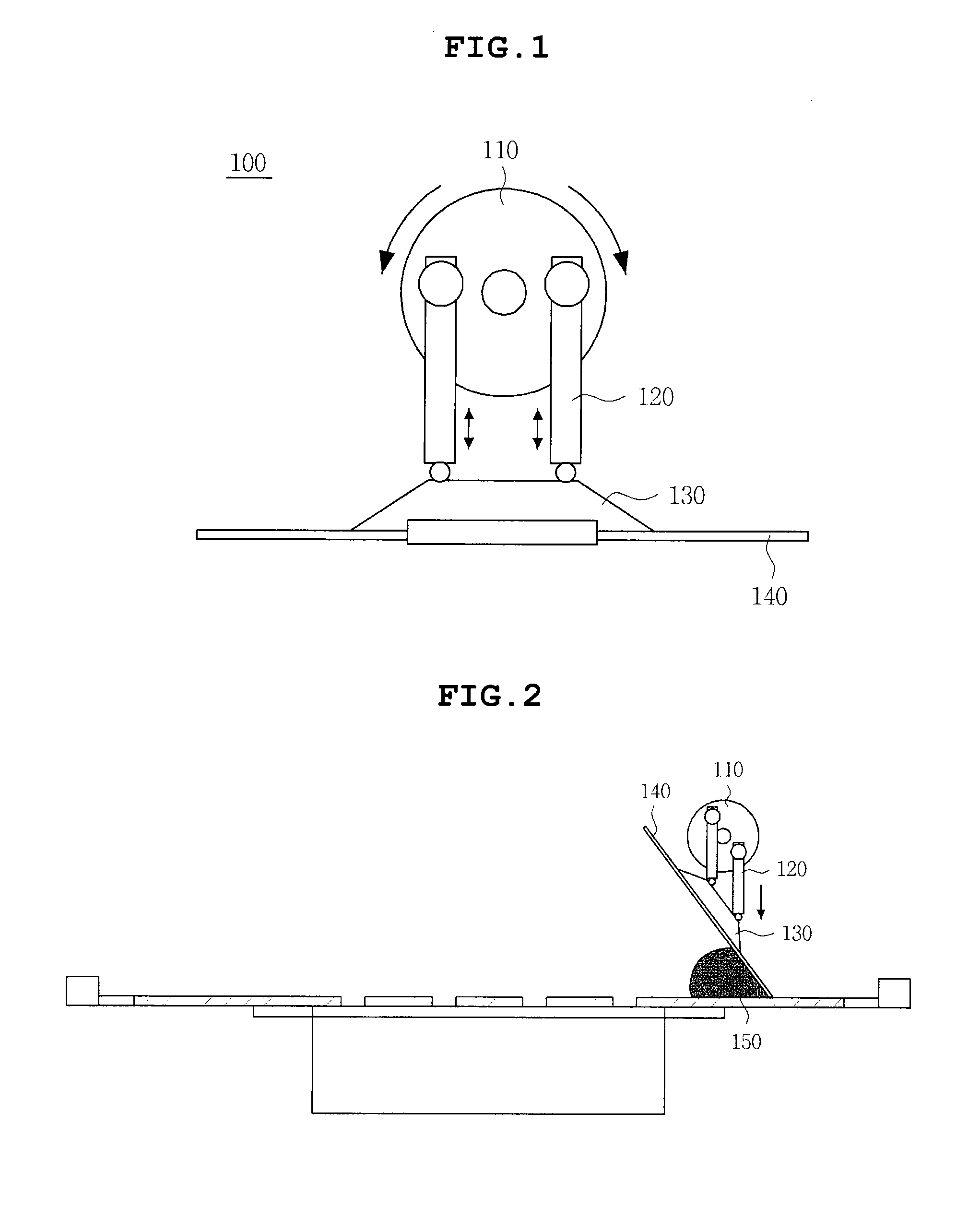
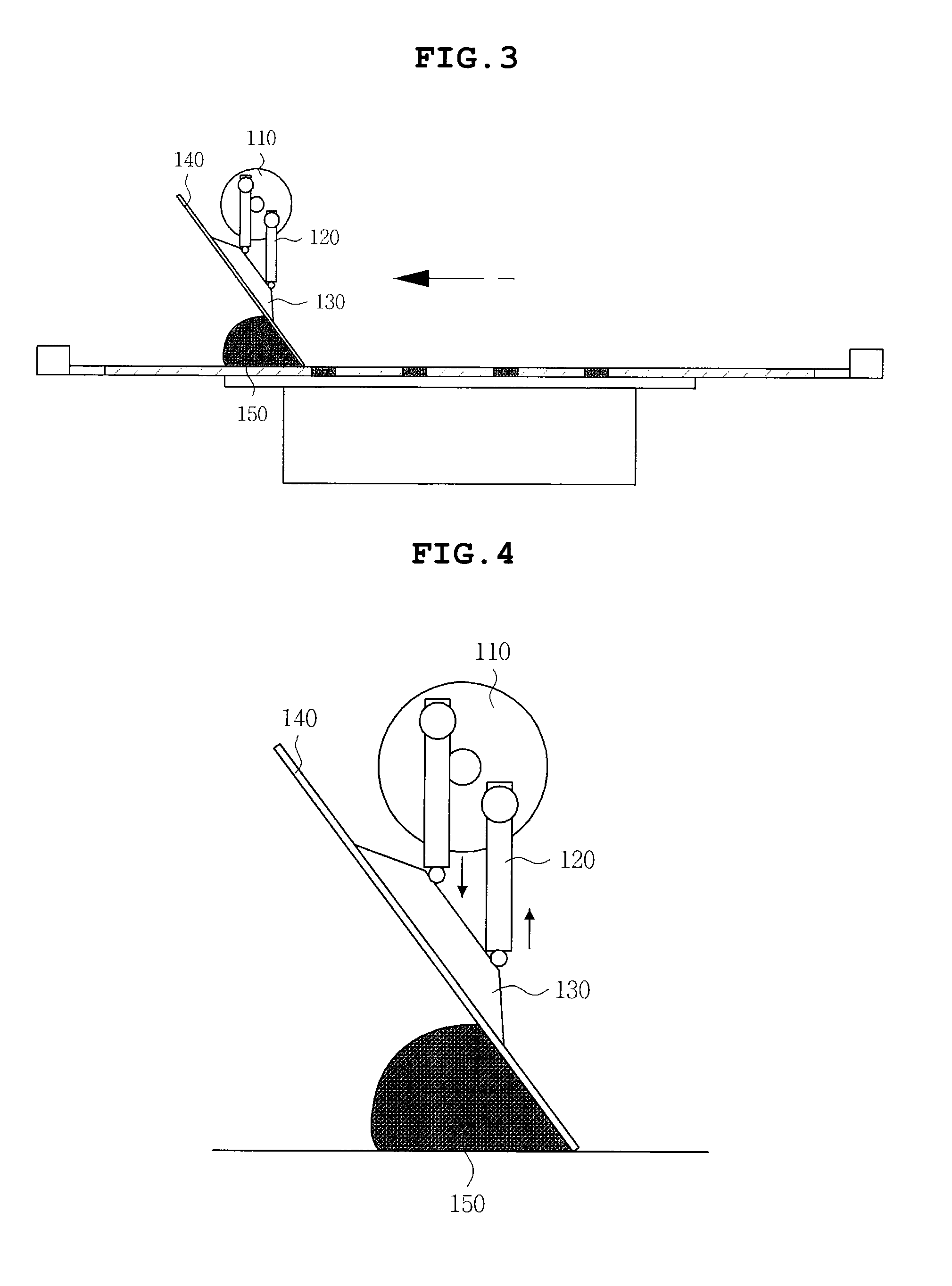
[0012]In one aspect of the present invention, there is provided a squeegee module, including: a rotary unit rotated in opposite directions; support rods mounted to the rotary unit on opposite sides of the center of the rotary unit; a squeegee holder connected to ends of the support rods; and a squeegee blade mounted to the squeegee holder, wherein the squeegee holder moves upwards and downwards in cooperation with the rotation of the rotary unit, thus controlling the inclination angle of the squeegee blade.
[0016]The squeegee module according to the present invention can continue the rolling of the solder paste and can maintain the constant properties of the solder paste after finishing one stroke printing, and can minimize the stroke used when rolling the solder paste.
[0017]Further, the squeegee module according to the present invention can prevent the drooping of the solder paste while the squeegee module is moving and can minimize the surface area of the solder paste that is exposed to the atmosphere, thus reducing the ill effect of atmospheric air and preventing the formation of voids in the solder paste.
[0018]Further, the squeegee module according to the present invention can execute the printing process while at the same time controlling the inclination angle of a squeegee blade in relation to a reduction in the amount of solder paste, thus continuously rolling of solder paste and thereby improving the quality of printing the solder paste.

Problems solved by technology

However, solder paste printing using the metal masks is problematic in that it may not attain the required bump quality standards, such as the height and shape of the bumps having the fine pitches, when it is used for forming the fine pitch bumps.
However, the squeegee-type deposition method may form voids in the solder paste and may not maintain the solder paste in the desired shape while the solder paste is being rolled, thus causing problems in addition to the difficulty of realizing the fine pitch bumps.
When the squeegee is moved upwards after one stroke of printing is finished, the part of the solder paste that has been rolled by the squeegee may adhere to the surface of the squeegee owing to the viscosity thereof and droops, thus losing the desired rolled shape.
In the above state, when the printing is restarted in a reverse direction, the squeegee module may not realize the desired printing quality due to the drooping solder paste.
However, in the above state, the amount of the remaining solder paste is not sufficient, so that the solder paste may assume a poor shape different from the previous rolled shape, thus reducing the bump quality.

Method used


Image

  • Squeegee module
  • Squeegee module
  • Squeegee module

Examples


Embodiment Construction

[0024]Various objects, advantages and features of the invention will become apparent from the following description of embodiments with reference to the accompanying drawings.

[0025]The terms and words used in the present specification and claims should not be interpreted as being limited to typical meanings or dictionary definitions, but should be interpreted as having meanings and concepts relevant to the technical scope of the present invention based on the rule according to which an inventor can appropriately define the concept of the terms to describe most appropriately the best method he or she knows for carrying out the invention.

[0026]The above and other objects, features and advantages of the present invention will be more clearly understood from the following detailed description taken in conjunction with the accompanying drawings. Herein, the same reference numerals are used throughout the different drawings to designate the same components. Further, when it is determined ...


PUM

PropertyMeasurementUnit
Angleaaaaaaaaaa
Shapeaaaaaaaaaa

Abstract

A squeegee module. The squeegee module of the present invention includes a rotary unit rotated in opposite directions, support rods mounted to the rotary unit on opposite sides of the center of the rotary unit, a squeegee holder connected to ends of the support rods, and a squeegee blade mounted to the squeegee holder, wherein the squeegee holder moves upwards and downwards in cooperation with rotation of the rotary unit, thus controlling the inclination angle of the squeegee blade.

Description

CROSS REFERENCE TO RELATED APPLICATION(S)[0001]This application claims the benefit of Korean Patent Application No. 10-2010-0082955, filed on Aug. 26, 2010, entitled “Squeegee Module”, which is hereby incorporated by reference in its entirety into this application.BACKGROUND OF THE INVENTION[0002]1. Technical Field[0003]The present invention relates to a squeegee module.[0004]2. Description of the Related Art[0005]In recent years, developments in the electronic industry have been accompanied by stronger demands being placed on the multifunctionality and smallness of electronic elements used in electronic apparatuses. Due to the trend to multifunctionalize and miniaturize electronic elements, bump pitches, formed on integrated circuits (IC) or on substrates, are required to be ultrafine and diversified. In the related art, a variety of methods of forming bumps on the substrates are being developed and widely used. An example of the bump forming methods generally used in the related a...

Claims


Application Information

Patent Timeline
IPC IPC(8): A47L1/06
CPCB23K1/0016B23K3/0607B23K3/08B23K2201/42H01L24/11H01L24/742H01L2924/014H01L2224/131H01L2924/01047H01L2224/1132H01L2924/01033H01L2924/14B23K2101/42H01L2924/00
Inventor PARK, YEO ILMUN, SEON JAEPARK, JUN HYEONGKIM, SEUNG WANKIM, SUN MOONKIM, DONG SUNBEAK, SEUNG HOLEE, CHANG HEE
Owner SAMSUNG ELECTRO MECHANICS CO LTD
Why Eureka
Try Eureka