
Fixing device and image forming apparatus

Inactive Publication Date: 2012-02-23
KONICA MINOLTA BUSINESS TECH INC
View PDF3 Cites 4 Cited by
  • Summary
  • Abstract
  • Description
  • Claims
  • Application Information

AI Technical Summary

Benefits of technology

[0016]The present invention has been achieved in view of the above problems, and aims to provide a fixing device and an image forming apparatus that can realize reduction in size, weight, and cost thereof without having a harmful effect such as uneven temperature distribution and reduction of heat generation efficiency, while preventing overheating in the regions where recording sheets do not pass through.

Problems solved by technology

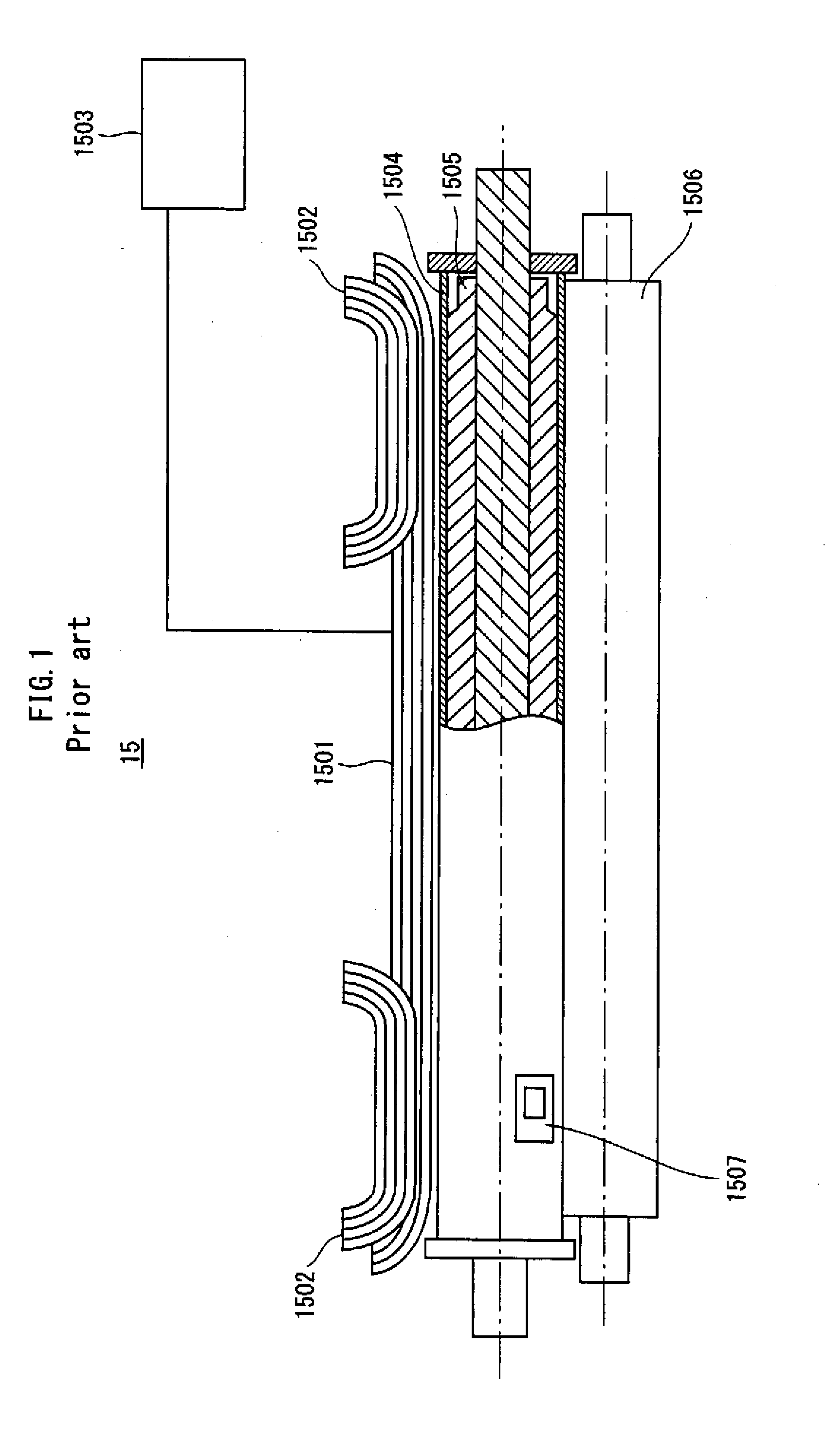
However, there is a problem in that if heating continues, the regions where small-size recording sheets do not pass through are overheated, which results in failure of the fixing device.
Therefore, for example, when small-size recording sheets pass through at a high speed, output of the excitation coil has to be large, and as a result, the demagnetization coils 1502 cannot effectively prevent overheating in the regions where the small-size recording sheets do not pass through.
Accordingly uneven fixation might occur.
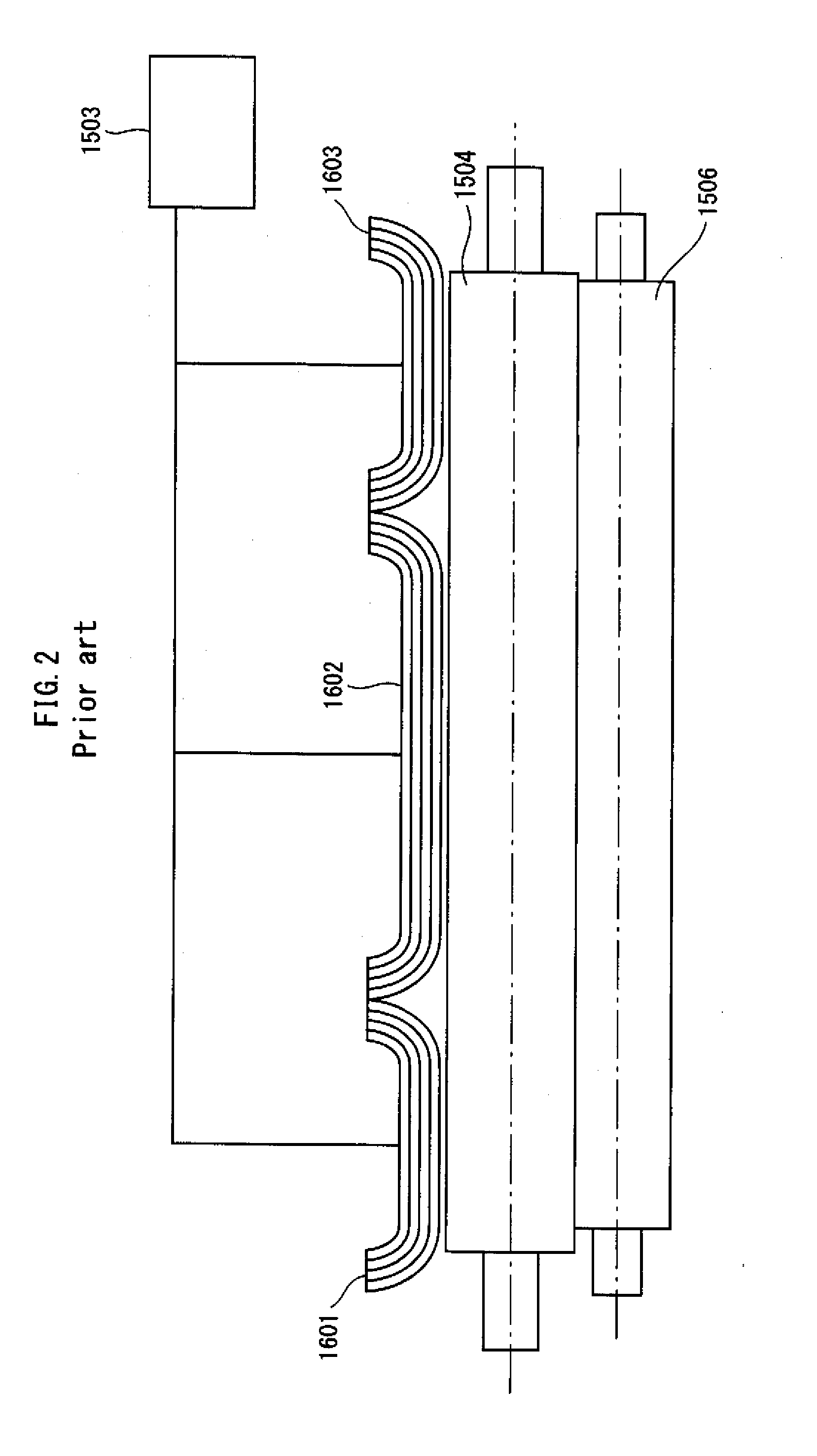
As a result, it is impossible to prevent reduction of heat generation efficiency of each of coils that correspond to different sizes of recording sheets (FIG. 6A).
In addition, if the excitation coils are made large, the fixing member also has to be large, and accordingly the fixing device becomes large.
Thus, each of the conventional arts has a different problem.

Method used


Image

  • Fixing device and image forming apparatus
  • Fixing device and image forming apparatus
  • Fixing device and image forming apparatus

Examples


Embodiment Construction

[0040]The following describes an embodiment of a fixing device and an image forming apparatus pertaining to the present invention, with reference to the drawings.

1. Structure of Image Forming Apparatus

[0041]Firstly, the following describes a structure of the image forming apparatus pertaining to the embodiment.

[0042]FIG. 7 shows a main structure of the image forming apparatus pertaining to the embodiment. As shown in FIG. 7, an image forming apparatus 1 includes a document reader 100, an image forming section 110, and a paper feeder 120. The document reader 100 generates image data by optically reading a document.

[0043]The image forming section 110 includes image forming units 111Y to 111K, a controller 112, an intermediate transfer belt 113, a secondary transfer roller pair 114, a fixing device 115, a sheet ejecting roller 116, an ejected-sheet tray 117, and a cleaner 118.

[0044]The image forming units 111Y to 111K respectively form toner images of yellow (Y), magenta (M), cyan (C) ...


PUM


Abstract

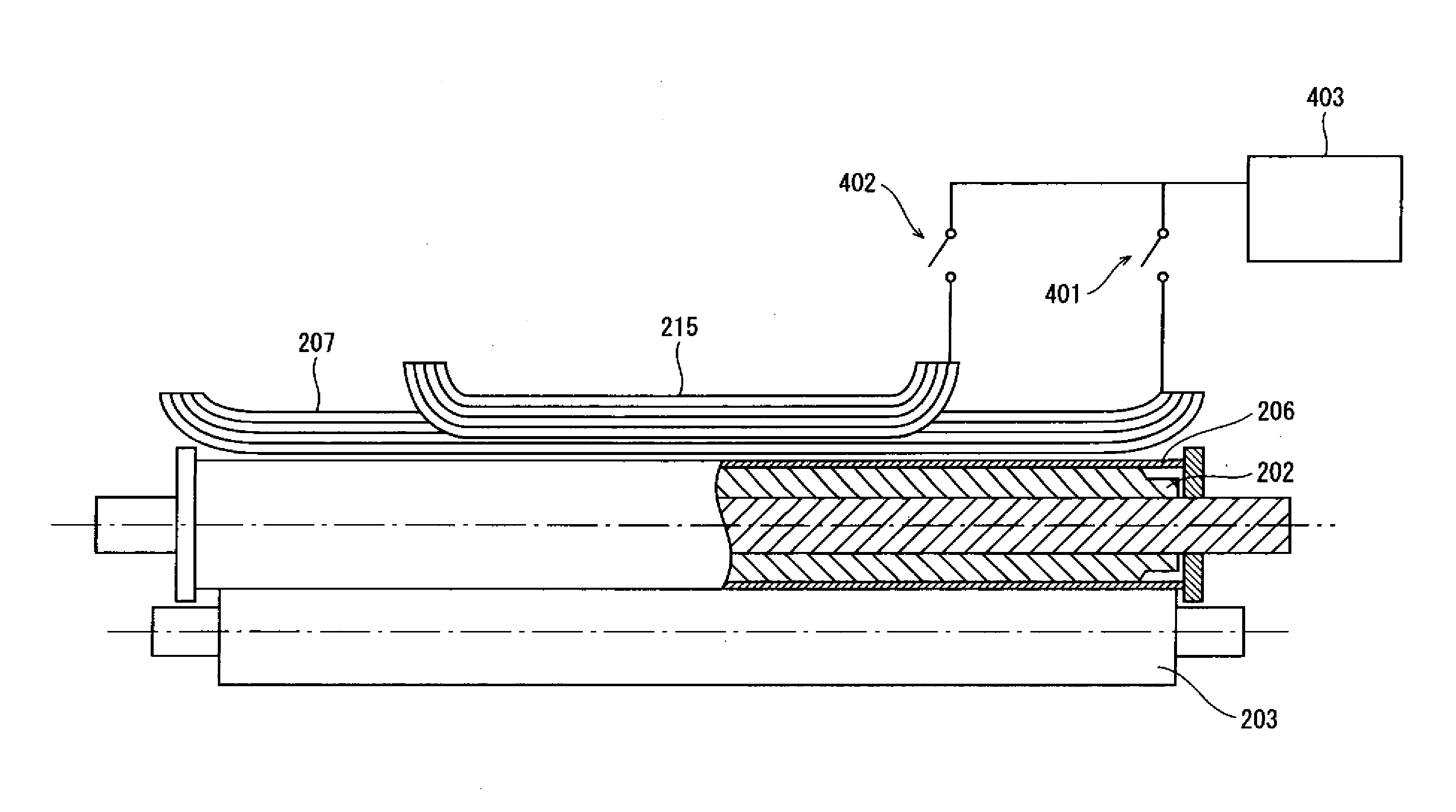
A fixing device including a fixing rotational body and fixing images on sheets of various sizes, comprising: a main excitation coil heating the rotational body by electromagnetic induction and having an effective heating length L1 corresponding to a maximum-size sheet; an auxiliary excitation coil having an effective heating length L2 shorter than L1; a high-frequency power source supplying power to the main and auxiliary coils; and a switch selectively connecting the main or auxiliary coils to the power source, wherein the main coil is positioned along an outer circumferential surface of the rotational body, the auxiliary coil is positioned farther from the rotational body than the main coil is and layered on a central portion of the main coil in a longitudinal direction thereof, and L2 satisfies the following relationship: L2≦L1·η2 / η1, where η1 and η2 are thermal conversion efficiencies of the main and auxiliary coils, respectively.

Description

[0001]This application is based on an application No. 2010-183733 filed in Japan, the contents of which are hereby incorporated by reference.BACKGROUND OF THE INVENTION[0002](1) Field of the Invention[0003]The present invention relates to a fixing device and an image forming apparatus, and in particular to a technology for preventing overheating in regions where recording sheets do not pass through, together with aiming to reduce size, weight, and cost of the device and the apparatus.[0004](2) Description of the Related Art[0005]In recent years, for electrophotographic image forming apparatuses, an electromagnetic induction-heating method has been actively studied to realize low heat capacity and improve temperature rise performance of a fixing member that fuses toner on recording sheets. The electromagnetic induction-heating method is used to heat the fixing member by applying induced current to a metal heat generating layer included in the fixing member with use of an excitation c...

Claims


Application Information

Patent Timeline
IPC IPC(8): G03G15/20
CPCG03G15/2064
Inventor SHIMIZU, YOSUKE
Owner KONICA MINOLTA BUSINESS TECH INC
Learn More