
Shading analysis software

Inactive Publication Date: 2012-02-09
SOLAR RED
View PDF0 Cites 150 Cited by
  • Summary
  • Abstract
  • Description
  • Claims
  • Application Information

AI Technical Summary

Benefits of technology

[0008]Additional embodiments may include a method of designing photovoltaic (PV) solar energy collector systems based on mapping shadows on a surface. Further embodiments may include a system for optimal positioning of solar panels to maximize energy production.

Problems solved by technology

There is a widespread concern that future energy supplies from coal, gas and oil may be volatile and unreliable and that these energy sources are sources of greenhouse gasses which may have detrimental environmental impact.
However, the high cost of deploying solar energy systems, particularly on rooftops and for small, distributed generation, is a significant barrier to end-user acceptance and to overall dissemination.
This method requires a physical presence at the proposed installation site and specialized equipment, as well as being time-consuming.
Because the data collection process must be performed for every proposed solar energy system installation to determine ultimate energy yield, the cost of this data collection adds a significant labor cost to solar energy system deployment costs.
Typically, only a limited number of positions are used because of time and resource constraints on the installer, resulting in gaps between data points.
Because of these gaps in the data set, a solar energy system design based on the data collected with current methodology may not actually result in optimal positioning of components such as solar panels.

Method used


Image

  • Shading analysis software
  • Shading analysis software
  • Shading analysis software

Examples


Embodiment Construction

[0010]In the following description, the term “solar energy system” may be used to refer to a system which converts solar (light) energy into another type of useful energy, such as electricity or heat. Examples of solar energy systems include, but are not limited to, photovoltaics (also referred to in the art as PV) and solar thermal systems. Photovoltaics convert light directly into electricity and are commonly referred to as photovoltaic panels, modules, or cells. Solar shingles may be photovoltaics in a form factor that allows the shingles to be installed with, and perhaps take the appearance of, shingles in a roofing system. Also available are peel-and-stick solar energy collectors that may cover, for example, an individual shingle. Solar thermal systems convert light energy into heat and use the heat for heating, cooling, or generating electricity. These products, and others like them, serve to collect energy from light. The various embodiments of the invention apply equally to ...


PUM


Abstract

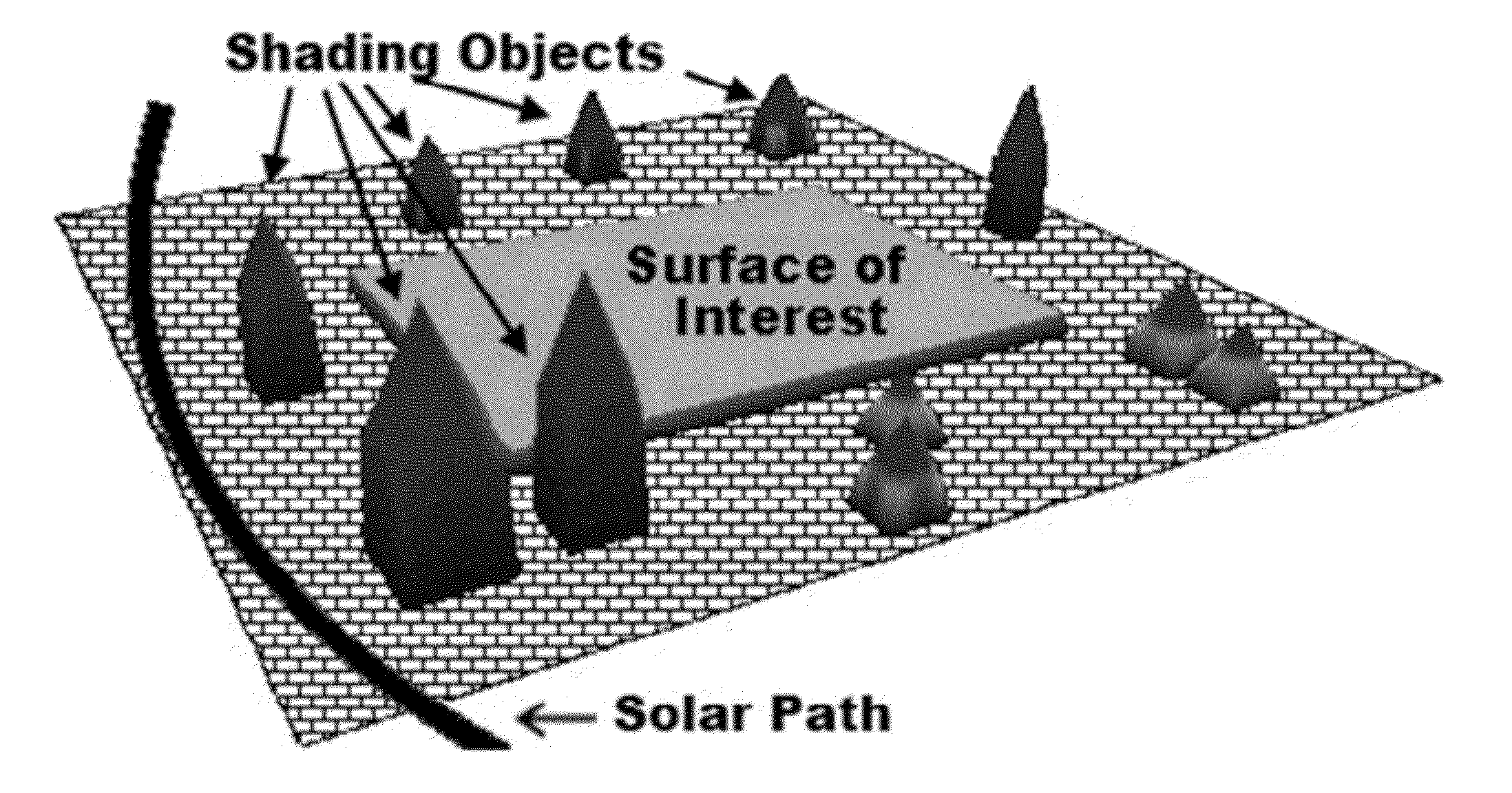
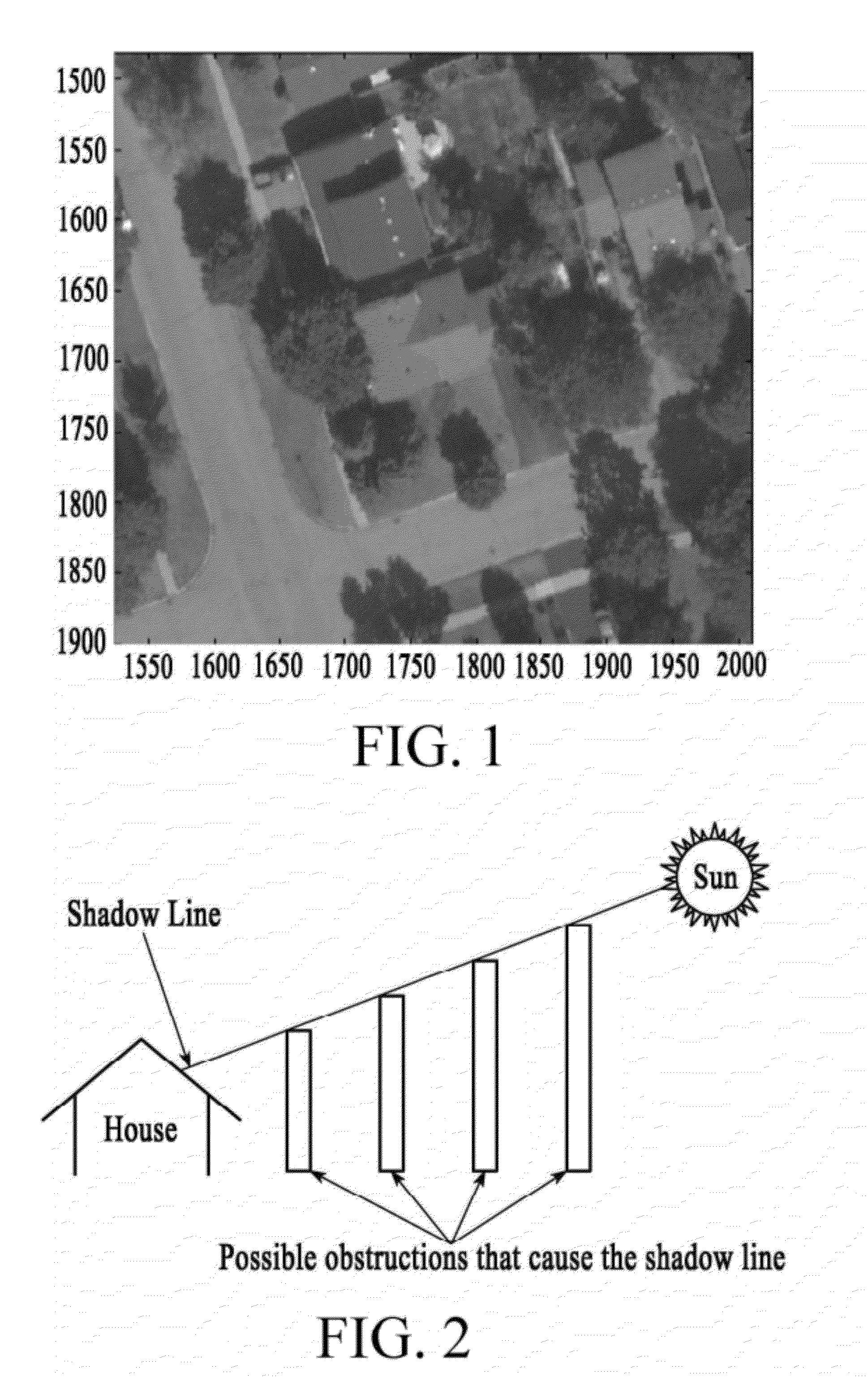
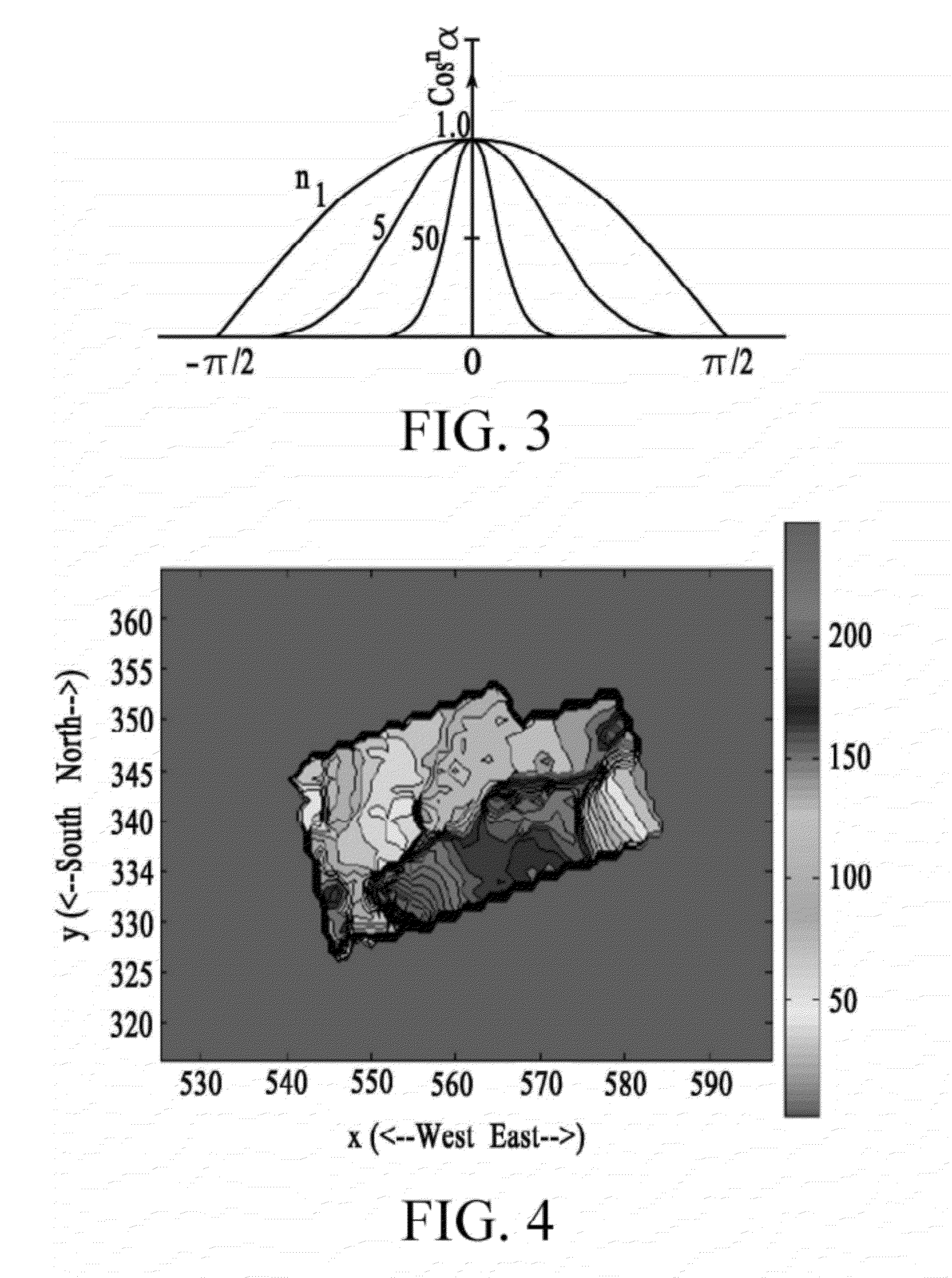
Systems and methods for shading analysis and creating a 3D model of a surface of interest are provided. Such systems and methods may include taking ray traces to determine light contact with the surface of interest. Shadow maps may be generated. Power flux calculations may also be performed.

Description

BACKGROUND OF THE INVENTION[0001]1. Field of the Invention[0002]The present invention relates generally to the field of solar energy. More specifically, various embodiments of the invention provide a process to collect data and analyze the light that falls on a surface of interest.[0003]2. Description of Related Art[0004]There is a widespread concern that future energy supplies from coal, gas and oil may be volatile and unreliable and that these energy sources are sources of greenhouse gasses which may have detrimental environmental impact. Demand for energy from non-polluting, renewable sources, such as solar energy, is rapidly growing. The widespread deployment of solar energy systems in the near-term is therefore highly desirable. However, the high cost of deploying solar energy systems, particularly on rooftops and for small, distributed generation, is a significant barrier to end-user acceptance and to overall dissemination.[0005]Solar energy systems require analysis of shading...

Claims


Application Information

Patent Timeline
IPC IPC(8): G06F17/50
CPCG06T15/06F24S2201/00G06T17/00G06T15/50
Inventor AUGENBRAUN, JOSEPHCAMMACK, KEVINJOHNSON, DEVON K.SUN, JIALINCHU, ALLARD C.
Owner SOLAR RED
Learn More