On-chip millimeter wave lange coupler

a millimeter wave and coupler technology, applied in waveguide devices, phase-modulated carrier systems, digital transmission, etc., can solve the problems of insufficient coupling between lines, large size and, therefore, much more expensive, and poor amplitude unbalan

Active Publication Date: 2012-02-09
GLOBALFOUNDRIES U S INC
View PDF3 Cites 0 Cited by
  • Summary
  • Abstract
  • Description
  • Claims
  • Application Information

AI Technical Summary

Benefits of technology

[0014]The illustrative aspects of the present disclosure are designed to solve the problems herein described and / or other problems not discussed.

Problems solved by technology

For on-chip implementations, branchline couplers exhibit a better amplitude balance than conventional Lange couplers but they are much larger in size and, therefore, much more costly.
Conventional on-chip Lange couplers utilize higher level metal layers for the signal traces so as to take advantage of the lower resistance loss, but the relatively larger minimum width and spacing of the design rule for those metal layers causes insufficient coupling among the lines and bad amplitude unbalance.

Method used


Image

  • On-chip millimeter wave lange coupler
  • On-chip millimeter wave lange coupler
  • On-chip millimeter wave lange coupler

Examples


Embodiment Construction

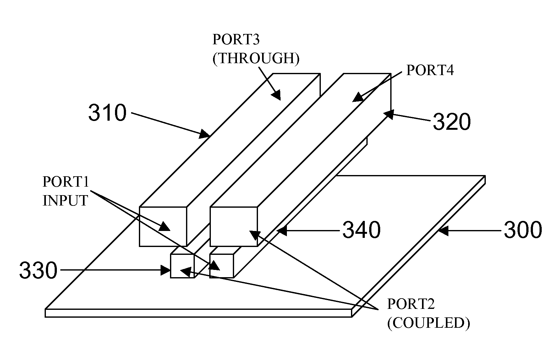
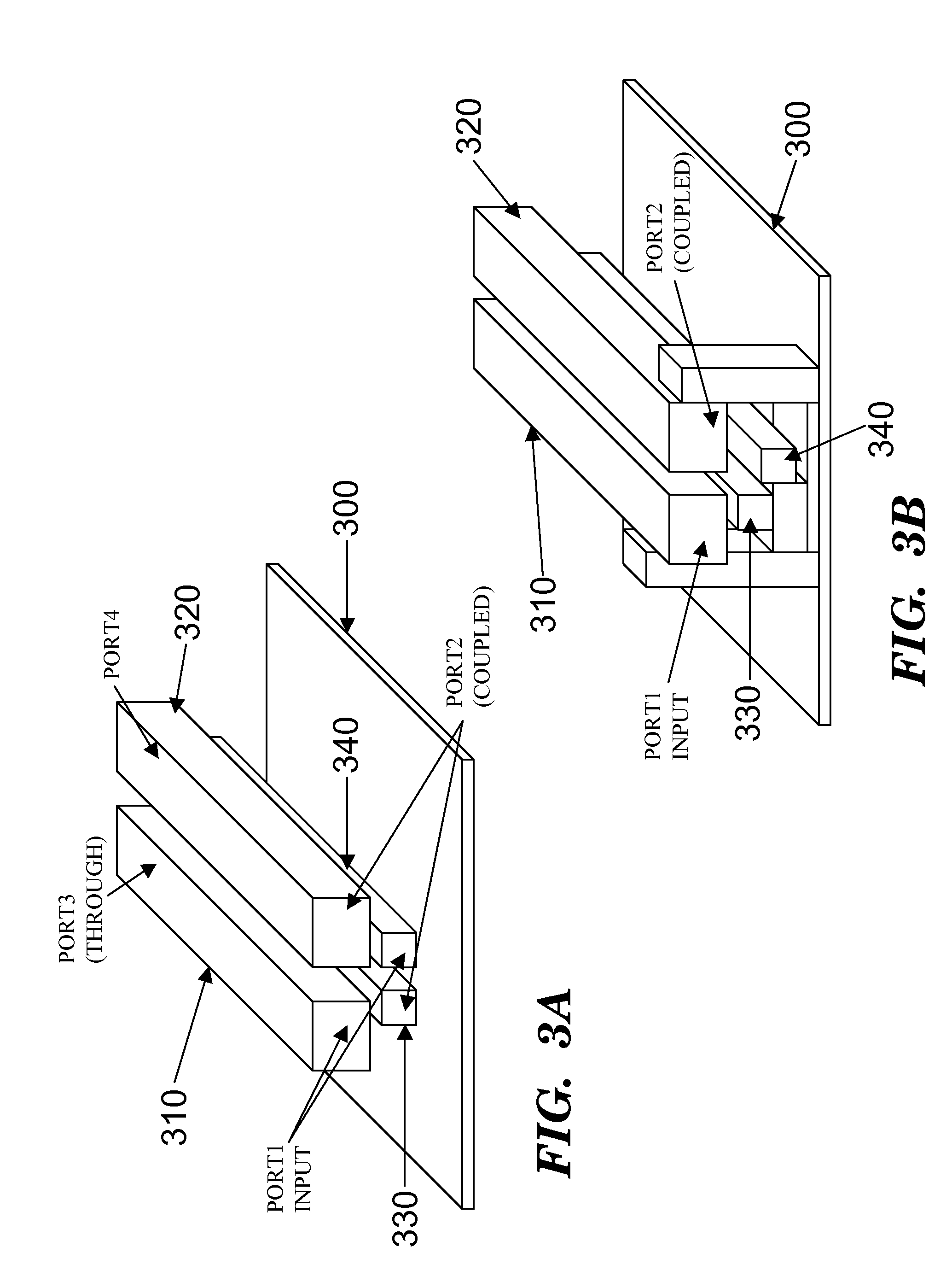
[0024]As indicated above, the disclosure provides an on-chip millimeter wave Lange coupler.

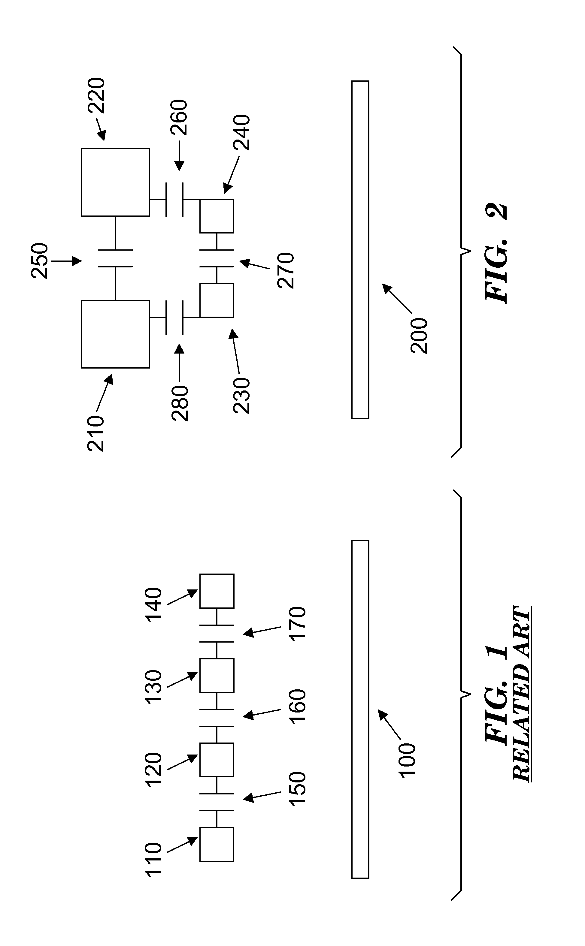
[0025]FIG. 1 shows a cross-section view of an on-chip Lange coupler in the related art. A substrate 100 has formed into it four lines or strips 110, 120, 130, and 140 that may be made of metal. For an on-chip implementation, all the lines 110, 120, 130, and 140 are on the same metal level. Lines 110 and 130 are connected with each other; and lines 120 and 140 are connected with each other. Capacitors 150, 160, and 170 denote where most of the electromagnetic coupling of electromagnetic waves traveling through the lines 110, 120, 130, and 140 occurs. The electromagnetic waves may be millimeter waves, for example. As can be seen in FIG. 1, very little coupling occurs between lines 110 and 140 at the far ends, for example. Once the minimum spacing and width of the lines are reached, there are no further options in this structure to improve the coupling between the lines.

[0026]FIG. 2 shows a cross...


PUM


Abstract

A Lange coupler having a first plurality of lines on a first level and a second plurality of lines on a second level. At least one line on the first level is cross-coupled to a respective line on the second level via electromagnetic waves traveling through the first and second plurality of lines. The first and second plurality of lines may be made of metal, and the first level may be higher than the second level. A substrate may be provided into which the first and second plurality of lines are etched so as to define an on-chip Lange coupler.

Description

CROSS-REFERENCE TO RELATED APPLICATIONS[0001]This application is a divisional of currently pending U.S. patent application Ser. No. 12 / 404,535 filed on Mar. 16, 2009. The application identified above is incorporated herein by reference in its entirety for all that it contains in order to provide continuity of disclosureBACKGROUND[0002]1. Technical Field[0003]The disclosure relates generally to Lange couplers, and more particularly, to an on-chip millimeter wave Lange coupler.[0004]2. background Art[0005]A 3 dB coupler having a 90° phase difference between the outputs of the 3 dB coupler is a very useful device in microwave and millimeter wave circuit design applications, such as high-frequency in-phase / quadrature (IQ) modulation and balanced amplifier structures. Such a 3 dB coupler can be realized, for example, as a branchline coupler or as a conventional Lange coupler. Normally, branchline couplers have a larger size and less frequency bandwidth than conventional Lange couplers, b...

Claims


Application Information

Patent Timeline
Patent Type & Authority Applications(United States)
IPC IPC(8): H03D3/00H03F3/68
CPCH01P5/186H03F3/68H03F3/602H03D3/007
Inventor DING, HANYILAM, KWAN HIM
Owner GLOBALFOUNDRIES U S INC
Why Eureka
Try Eureka