
Zipline Trolley System

a trolley system and zipline technology, applied in the direction of rope railways, locomotives, roads, etc., can solve the problems of increasing the length of time required, not always ensuring that the user is placed in a loaded position, and complicating the process of starting and ending rides

Active Publication Date: 2012-02-09
SKYLINE ZIPLINE GLOBAL
View PDF29 Cites 21 Cited by
  • Summary
  • Abstract
  • Description
  • Claims
  • Application Information

AI Technical Summary

Benefits of technology

[0005]According to one aspect of the invention, a zipline trolley system comprises a cable extended between a first point and a second point, a trolley, a launcher fixed to the first point, and a catch block fixed to the second point. The trolley comprises one or more wheels that travel on the cable and a frame attached to the one or more wheels, wherein the frame comprises a front plate and a back plate. The launcher comprises a substantially cylindrical inner body fixed t...

Problems solved by technology

This system is simple, yet it is not always ensured that the user is placed in a loaded, secure position before the trolley is released from the starting point.
This can lead to catastrophic results if improper connections are not detected before the trolley is released.
These added procedures at the departure and arrival of every zipline trolley both increase the length of time required for each user to experience the zipline system and complicate the process for starting and ending rides on the zipline trolleys.

Method used


Image

  • Zipline Trolley System
  • Zipline Trolley System
  • Zipline Trolley System

Examples


Embodiment Construction

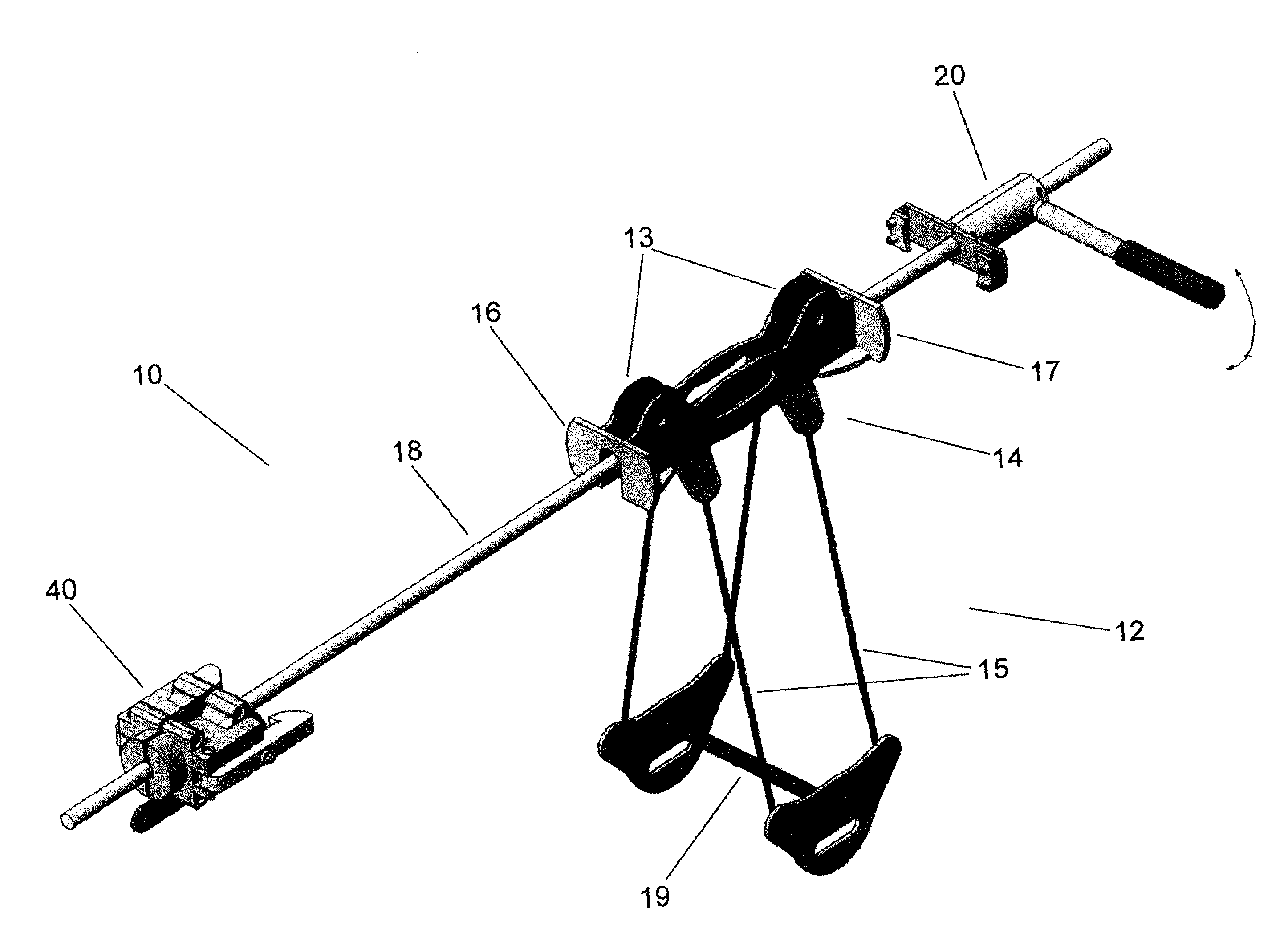
[0016]Referring to FIG. 1, the zipline trolley system 10 of the present invention comprises a trolley 12 that travels along a cable 18. At one end of the cable 18 is attached a launcher 20, which is used to start the trolley 12 moving along the cable 18. At the other end of the cable 18 is attached a catch block 40, which is used to stop the trolley 12. Preferably, both the launcher 20 and the catch block 40 are elevated above ground, with the launcher 20 elevated higher than the catch block 40 so that the trolley 12 will move, through gravity, from the launcher 20 to the catch block 40 along the cable 18.

[0017]The cable 18 may be a steel cable of any suitable diameter. Preferably, the diameter of the cable 18 is one inch or less. The trolley 12 comprises one or more wheels 13 enclosed in a frame 14. The wheels 13 travel on top of the cable 18, and lines 15 extend from the sides of the frame 14 to attach to a handle 19 that swings below the frame 14. The handle 19 is attached to a u...


PUM


Abstract

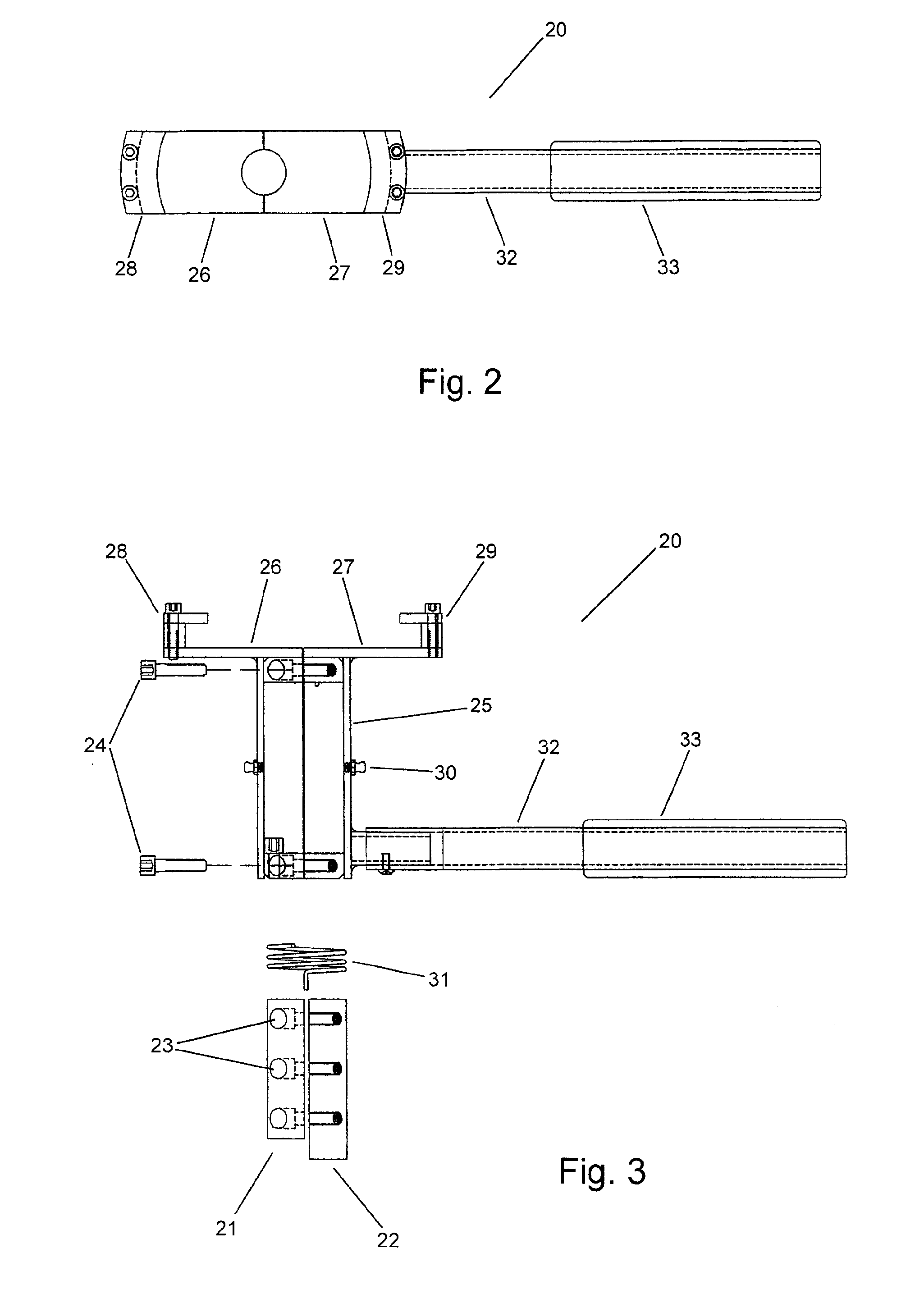
A zipline trolley system comprises a cable, trolley, launcher, and a catch block. The launcher is fixed on the cable and comprises a substantially cylindrical inner body with a rigid outer body adapted to rotate about the inner body. A return spring attaches the inner body with the outer body. The catch block is also fixed on the cable and comprises a block with left and right retaining arms pivotably connected to the block and adapted to clasp onto the front plate of the frame of the trolley.

Description

FIELD OF THE INVENTION[0001]The present invention relates to zipline trolley systems. More particularly, the invention relates to launching and braking devices for zipline trolley systems.BACKGROUND OF THE INVENTION[0002]Zipline trolley systems typically comprise a small trolley that rolls freely along a cable extended between two points. The two points are typically elevated from the ground, with the starting point elevated higher than the finishing point. At the starting point, the user is attached to a trolley (such as the one described in U.S. patent application Ser. No. 12 / 239,959, the contents of which are hereby incorporated by reference) and sent down the cable. The user is usually attached to the trolley through a number of steel carabiners. At the finishing point, the user is disengaged from the trolley. This system is simple, yet it is not always ensured that the user is placed in a loaded, secure position before the trolley is released from the starting point. This can l...

Claims


Application Information

Patent Timeline
IPC IPC(8): B61B3/00
CPCB61H9/02B61B7/00A63G21/22B61B12/00A62B1/18B61B3/00
Inventor SMITH, KEVIN G.
Owner SKYLINE ZIPLINE GLOBAL
Learn More