Body having a dedicated lens for imaging an alignment feature

a technology of alignment feature and body, applied in the field of alignment of articles, can solve the problems of high cost, difficult alignment of devices such as these to optical fibers, and relatively complicated optical structures,

Active Publication Date: 2012-02-02
TE CONNECTIVITY CORP
View PDF1 Cites 37 Cited by
  • Summary
  • Abstract
  • Description
  • Claims
  • Application Information

AI Technical Summary

Benefits of technology

[0013]Another aspect of the present invention provides a method for preparing an optical subassembly. The method includes providing a substrate supporting a light source having optical axis, the substrate further comprising at least one alignment feature provided in a predetermined spatial relationship to the light source, providing a lens body having an alignment structure having a viewing surface, positioning the lens body on the substrate s...

Problems solved by technology

These devices have certain benefits, and alignment of devices such as these to optical fibers has proved relatively difficult, requiring relatively complicated optical structures and paths to effect the coupling.
A problem with active alignment techniques is that the process requires special imaging equipment and can be expensive, particularly with respect to light bending optical couplings.
However, this method requires additional hardware and fixturing to properly view the alignment features, due to tight spacing constraints in the OED assembly.
Additionally, this technique is unsafe in that any accidental activation of the light sources will cause damage to the human eye used during the alignment process, since the optical path...

Method used


Image

  • Body having a dedicated lens for imaging an alignment feature
  • Body having a dedicated lens for imaging an alignment feature
  • Body having a dedicated lens for imaging an alignment feature

Examples


Embodiment Construction

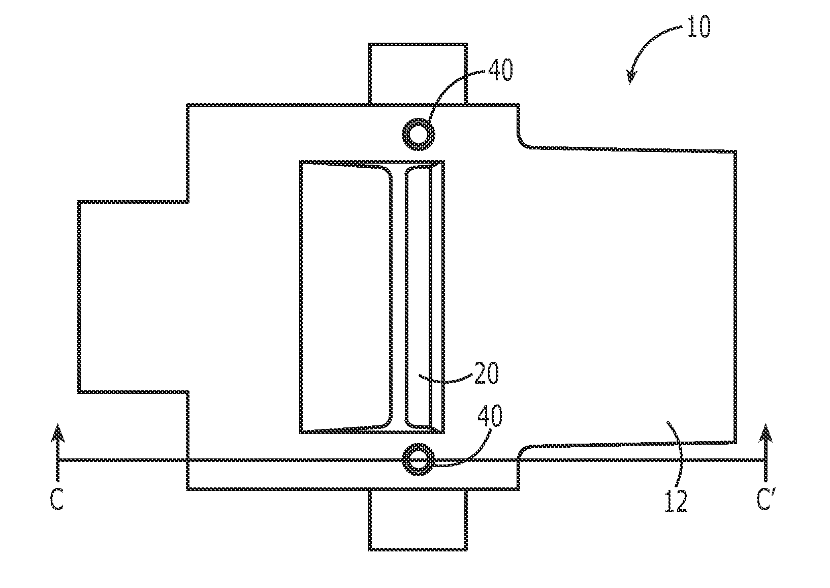
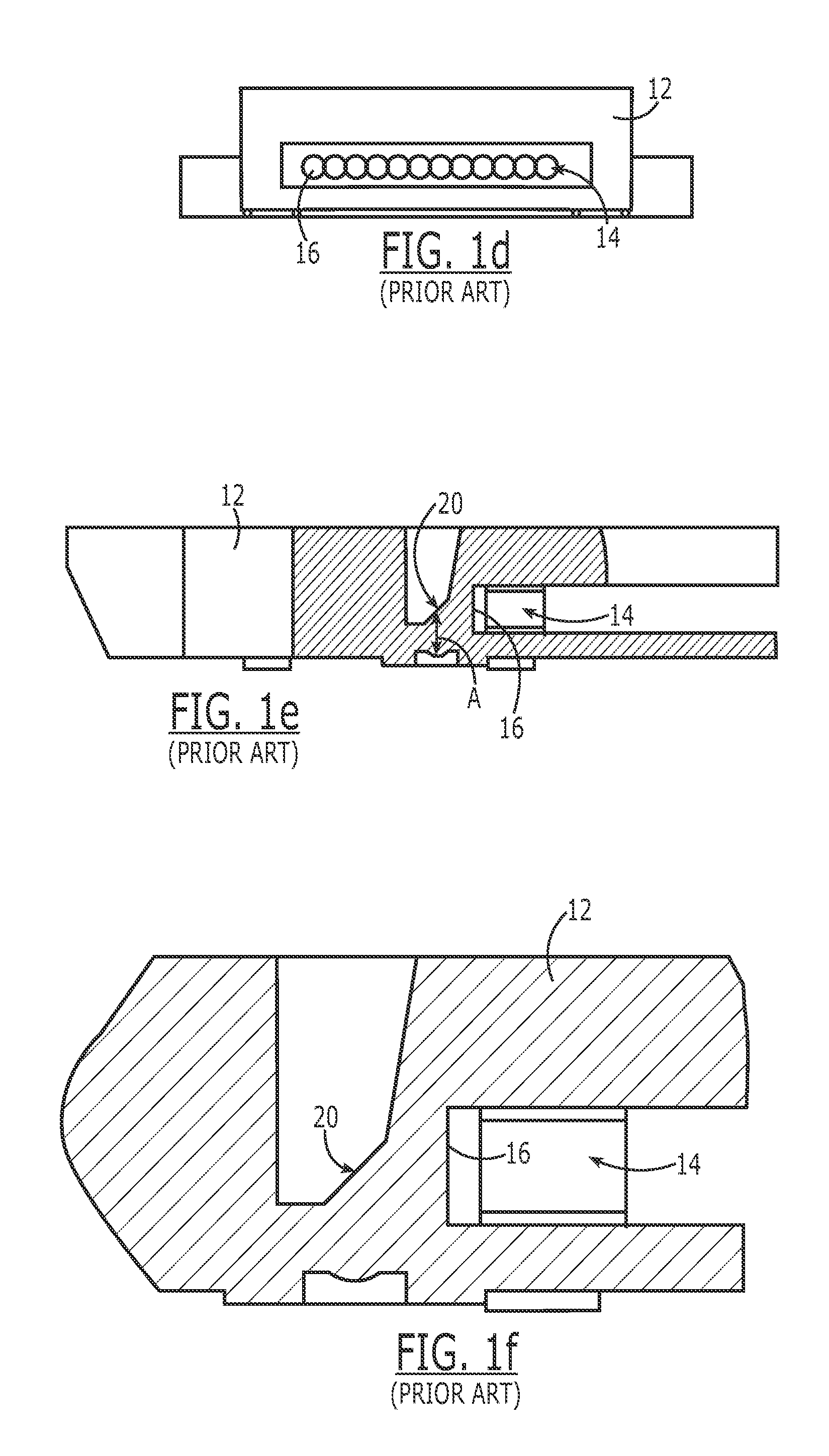
[0028]For illustrative purposes, the present invention is discussed below in the context of a lens body. As discussed above, FIGS. 1a-1f show an exemplary lens body 10 that has features in common with prior art lens bodies. The illustrated lens body 10 includes a body 12 that is exemplary of many prior art lens bodies in that it includes a bottom surface 26 for abutting a substrate supporting one or more OEDs (such as VCSELs), a port 14 for receiving one or more optical fibers for carrying light to or from the OEDs, a lens 24 corresponding to each OED for focusing light from the OEDs onto an interface surface 16 of the port 14 and into optical fibers abutting the interface surface 16 (or vice versa), and a reflective surface 20 for reflecting light transmitted between the OEDs and the optical fibers abutting the interface surface 16. As used here, “abutting” or “interfacing” means physically contacting in abutting relationship or nearly in physical contact, e.g., separated by a gap ...


PUM


Abstract

A body is configured for alignment to a substrate having an alignment feature. The body includes an alignment structure defining a viewing surface, and a dedicated lens adapted to focus an image of the substrate's alignment feature through an optically-clear material of the body and onto the viewing surface. In the fiber optic context, a lens body is provided for optically coupling a substrate's OED to a corresponding optical fiber. The lens body further includes at least one active lens adapted to cooperate optically with a respective OED. The dedicated lens is positioned externally to any optical path. An optical subassembly includes a substrate having at least one perceptible alignment feature provided in a predetermined spatial relationship to the OED, and a lens body secured to the substrate such that the image of the substrate's alignment feature appears aligned relative to the viewing surface.

Description

FIELD OF INVENTION[0001]The present invention relates generally to alignment of articles into an operative position, such as alignment of coupling devices for optically coupling a fiber optic cable and an opto-electronic device, and more particularly to a lens body having at least one dedicated lens for focusing an image of a substrate alignment feature onto an alignment structure on the lens body, for the purpose of properly aligning the lens body with opto-electronic devices on the substrate.BACKGROUND[0002]Typical fiber optic connectors require a coupling device which effectively optically couples the fiber optic transmission line with an opto-electronic device (OED). The OED is further electronically coupled to electronic circuits which operate in conjunction with the OED. Often, such electronic circuits, including integrated circuits, are mounted on a printed circuit board or ceramic substrate. To accommodate the use of optical transmission devices in densely packed parallel ar...

Claims


Application Information

Patent Timeline
IPC IPC(8): G02B6/32G02B6/00
CPCG02B6/3885G02B6/4206G02B6/4292G02B6/4224G02B6/4249G02B6/4214
Inventor CASTAGNA, LOUMILLER, RICHARD DEANGILLIS, DANIELDELLINGER, DONALD EUGENE
Owner TE CONNECTIVITY CORP
Why Eureka
Try Eureka