Wafer cutting tool

Inactive Publication Date: 2012-02-02
SCHENA KENNETH R
View PDF18 Cites 4 Cited by
  • Summary
  • Abstract
  • Description
  • Claims
  • Application Information

AI Technical Summary

Benefits of technology

[0004]The inventive concept is designed to cut a precision round hole in a variety of sizes to facilitate a comfortable fit which is free of abrasive edges and it is done with a minimal of effort. The base can be made from a variety of materials and the cutter is machined from stainless steel with a razor sharp cutting edge to facilitate fast easy customizing of the wafer.

Problems solved by technology

Often the scissor cut will leave rough edges that can rub against the stoma resulting in bleeding.

Method used


Image

  • Wafer cutting tool
  • Wafer cutting tool
  • Wafer cutting tool

Examples


Embodiment Construction

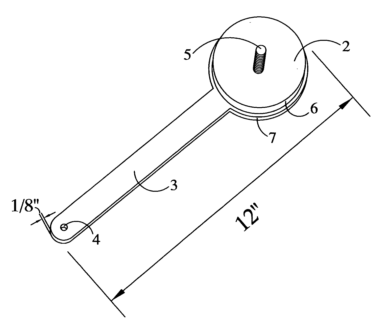
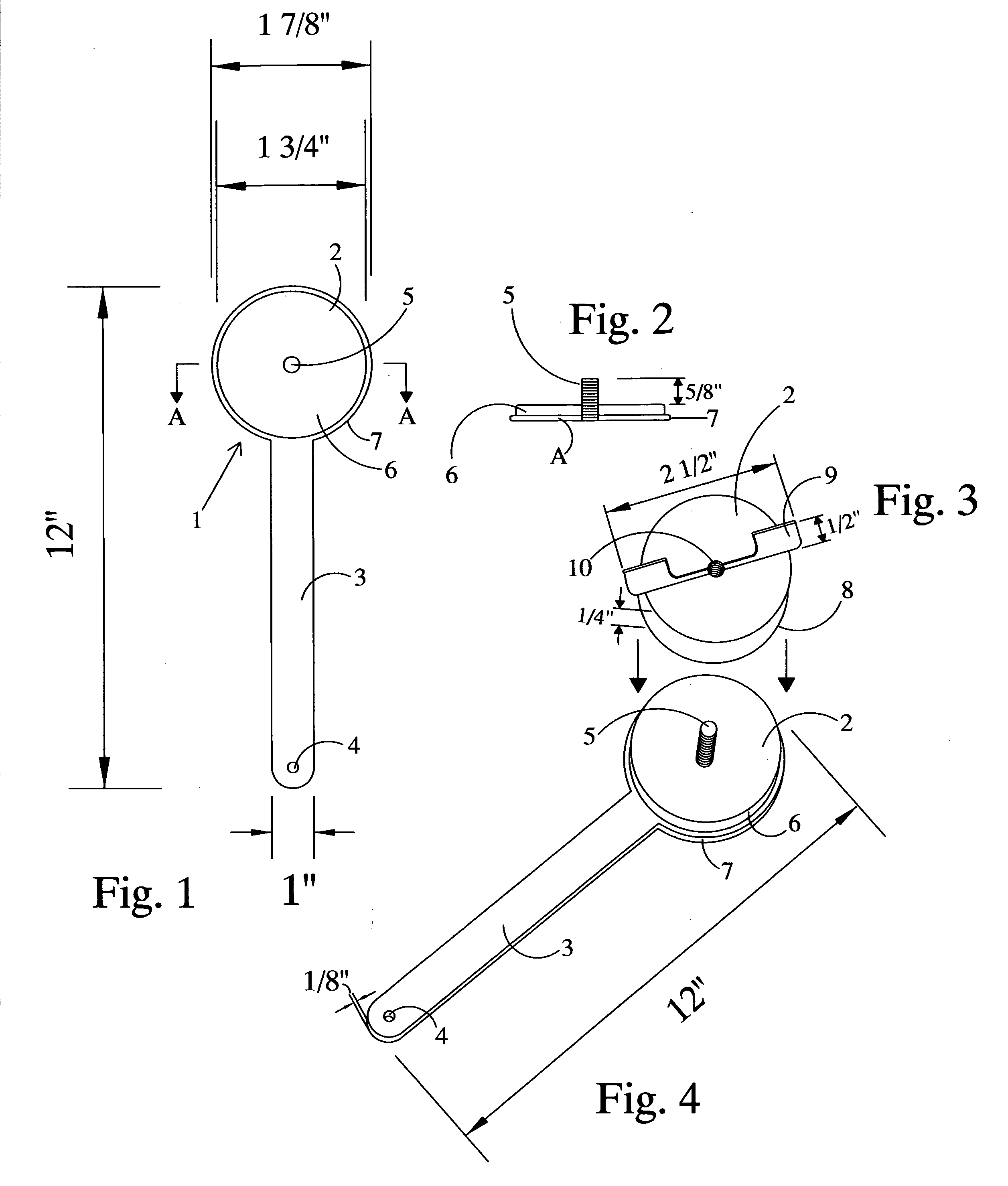
[0010]FIG. 1 shows a top view of the cutting tool 1. The tool 1 has at one end thereof a circular base 2 which is the backup disc when a material is being cut, as will be described below. The tool 1 has a handle 3 therein that is being used to handle the tool 1 in certain circumstances. The handle 3 has at one end thereof a hole 4 that is used to store the cutter 1 when not in use, like hanging it up. Also shown at the other end of the cutting tool there is a cutting location 7 which consists of the disc 2 in the form of a circular base as a back up such as a stainless steel. On top of the disc 2 there is located a NYLON disc 6 which forms the backup when a wafer is being cut.

[0011]FIG. 2 is a side view along the view of AA of the cutting instrument, especially at the cutting end 2 of the tool 1. FIG. 2 shows the back-up plate 7 which receives a threaded rod 5 in its center. The back-up plate 7 has a NYLON plate 6 placed thereon. The plate 6 is the plate which will receive the cutti...


PUM


Abstract

The inventive concept is directed to a circular cutting device, especially designed or used in cutting circular wafer in an ostomy application. The device consists of a handle having at one end thereof a circular backup plate. On top of the backup plate is located a plastic cutting receiving plate. The circular backup plate has at its center a threaded rod to receive a circular cup thereon. The cup has at its lower circular edge a razor-like cutting edge which will cut a perfect wafer when screwed down onto the plastic cutting receiving plate by way of the threaded rod.

Description

BACKGROUND OF THE INVENTION[0001]There is a population of people that have undergone operations that have resulted in the establishment of what is called stoma. The stoma is a part of the colon or upper digestive track that has been routed through a hole that is cut by the surgeon in the abdominal wall to permit the expulsion of body waste. This bowel diversion can have resulted from any one number of causes including, but not limited to, cancer diverticulitis. Crones disease may be result of this type of surgical correction. The resulting surgery has created the need for a collection system to provide for the human body waste that can be expelled and must be collected for appropriate disposition.[0002]There are a variety of pouch collection systems that have been designed to accommodate surrounding the stoma created to facilitate accumulation and disposal of this waste. The pouch systems come in one or two piece models that have a wafer and a bag. The two piece systems have two sep...

Claims


Application Information

Patent Timeline
IPC IPC(8): B26B25/00
CPCA61B17/32053A61B17/32093A61F5/445A61B2017/320052A61B2017/00818
Inventor SCHENA, KENNETH R.
Owner SCHENA KENNETH R
Why Eureka
Try Eureka