
Utility cover identification system

a technology for identification systems and utility covers, applied in the field of utility covers, can solve the problems of increasing the cost and storage space for maintaining inventory, reducing the efficiency of use, and reducing the efficiency of use, and achieve the effect of convenient installation

Active Publication Date: 2012-01-19
HUBBELL INC
View PDF10 Cites 14 Cited by
  • Summary
  • Abstract
  • Description
  • Claims
  • Application Information

AI Technical Summary

Benefits of technology

[0008]Accordingly, it is an object of the present invention to provide identification indicia for a utility cover that is easily installed. It is another object of the present invention to provide identification indicia that are installable in a variety of utility covers. It is yet another object of the present invention to provide identification indicia to withstand the exposed-environment lifecycle of the utility cover.

Problems solved by technology

While these methods may be potentially cost-efficient for large production runs, cost efficiency decreases as size of the production run decreases.
Correspondingly, the cost and storage space for maintaining inventory increases with the variety of identification indicia and the variety of sizes of utility covers.
But if the surface or recess are not clean and dry, the adhesive may not hold.
Additionally, if the adhesive and identification plate are applied further down the supply chain, for example, at a distributor, and the distributor does a sloppy glue job, such actions may reflect on and cause problems for the manufacturer.
Further, such glued-on identification plates may come off and / or crack from thermal expansion and contraction.
Other methods for attaching identification plates to covers include fasteners, such as rivets, bolts, and other through-fasteners, but such methods increase the time and labor required, and thus the cost of producing such covers.
Moreover, material choices for such covers may provide additional difficulties.
Obtaining sufficient dimensional accuracy to ensure retention of such identification plates may be difficult in materials that are suitable for the exposed-environment lifecycle of such utility covers.

Method used


Image

  • Utility cover identification system
  • Utility cover identification system
  • Utility cover identification system

Examples


second embodiment

[0026]FIG. 13 is a bottom plan view of a tray in accordance with the present invention;

[0027]FIG. 14 is a side elevational view of the tray of FIG. 13;

[0028]FIG. 15 is a vertical cross-sectional view in right end elevation of the tray of FIG. 13 taken along line 15-15 in FIG. 13;

[0029]FIG. 16 is a vertical Cross-sectional view in side elevation of a utility cover and the tray of FIG. 13;

third embodiment

[0030]FIG. 17 is a bottom plan view of the tray in accordance with the present invention;

[0031]FIG. 18 is a side elevational view of the tray of FIG. 17;

[0032]FIG. 19 is a right end elevational view of the tray of FIG. 17;

fourth embodiment

[0033]FIG. 20 is a bottom plan view of the tray in accordance with the present invention;

[0034]FIG. 21 is a side elevational view of the tray of FIG. 20;

[0035]FIG. 22 is a right end elevational view of the tray of FIG. 20;


PUM

PropertyMeasurementUnit
Shapeaaaaaaaaaa
Contraction enthalpyaaaaaaaaaa
Thermal expansion coefficientaaaaaaaaaa

Abstract

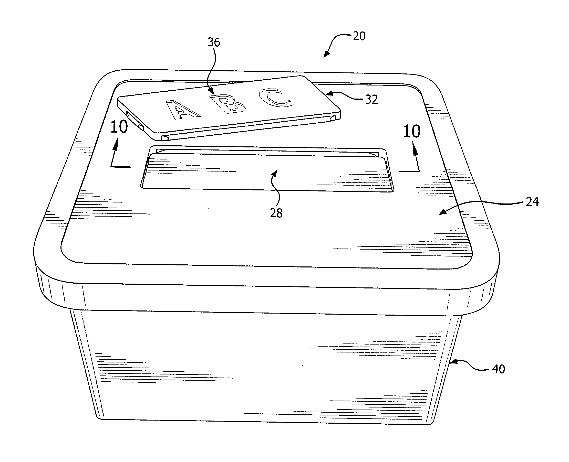
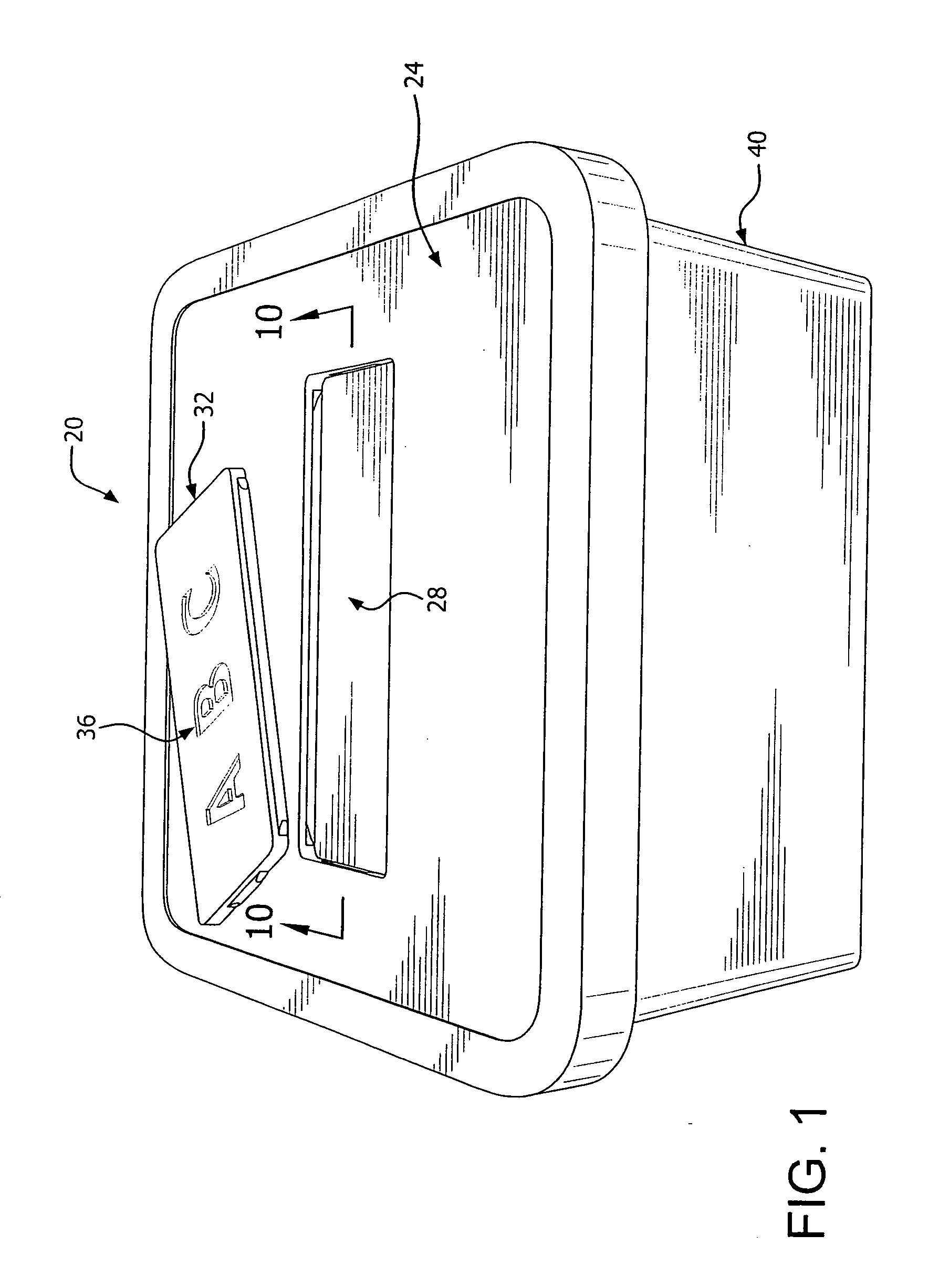
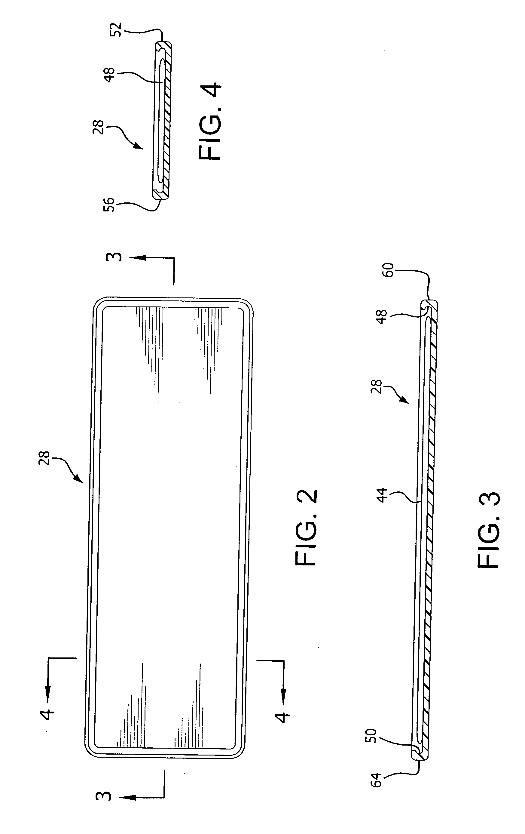
A utility cover identification system including a cover, a tray having a recess and being embedded within the cover, and an identification plate insertable into the tray to engage the tray recess to retain the identification plate within the tray. A method of forming the cover identification system includes the steps of coupling the cover and a tray together, curing the cover to secure the tray to the cover, and inserting an identification plate into the tray and retaining the identification plate in the tray.

Description

BACKGROUND OF THE INVENTION[0001]1. Field of the Invention[0002]The present invention relates to utility covers, and more particularly, to utility cover identification systems.[0003]2. Description of the Related Art[0004]Identification indicia, such as company and other organization logos, trademarks, service marks, product names, and product or utility classifications have heretofore been applied to products in a variety of manners. Effective methods for applying such identification indicia to utility covers include painting, silk-screening, molding, embossing, and engraving. While these methods may be potentially cost-efficient for large production runs, cost efficiency decreases as size of the production run decreases. Correspondingly, the cost and storage space for maintaining inventory increases with the variety of identification indicia and the variety of sizes of utility covers.[0005]Accordingly, plates bearing identification indicia (hereinafter identification plates) that a...

Claims


Application Information

Patent Timeline
IPC IPC(8): B65D85/00B65B7/28B65D51/00
CPCB25H3/02B65D2203/00B65D43/0202B65D25/205B65D51/245B29C39/10B29C65/48B29C65/66B29C66/02242B29L2017/00B29L2031/712
Inventor SCHWEINBERG, FRED MATTHEWCASTLE, STEVE A.FISHER, MIKE E.MIKES, MARK E.SLATER, ERIC M.TIPTON, WILEY R.
Owner HUBBELL INC
Learn More