Sheet conveying apparatus and image forming apparatus

a conveying apparatus and forming apparatus technology, applied in the direction of electrographic process apparatus, thin material processing, instruments, etc., can solve the problems of sheet misalignment in a direction orthogonal, sheet skewed and fed, sheet misalignment, etc., to achieve convenient assembly and low cost. , the effect of simple configuration

Inactive Publication Date: 2012-01-05
CANON KK
View PDF6 Cites 6 Cited by
  • Summary
  • Abstract
  • Description
  • Claims
  • Application Information

AI Technical Summary

Benefits of technology

[0012]The present invention provides a sheet conveying apparatus which has a position detecting apparatus which can precisely detect a position with a cheap and simple configuration which is easy to assemble, and an image forming apparatus.
[0014]According to the present invention, when an aperture stop is provided between light emitting portion and a light receiving portion, so that it is possible to precisely detect a position of the end part with a cheap and simple configuration which is easy to assemble.

Problems solved by technology

However, with the above skew feeding which is performed by having the front end of a sheet hit the shutter member, although it is possible to perform skew feeding correction of conveying sheets virtually parallel to the sheet conveying direction, it is not possible to correct the position of the sheet misaligned in a direction orthogonal to the sheet conveying direction.
Therefore, the second face is susceptible to the influence of various rollers and conveying guide.
By this means, sheets are likely to be skewed and fed, or misaligned.
Therefore, there is a problem that cost of sensors becomes high, and, as a result, cost of the entire apparatus becomes high.
According to Japanese Patent Laid-Open No. 62-40475, while a detecting portion which is provided with a plurality of sensors aligned in a width direction is moved according to a sheet size and therefore the number of sensors is comparatively a little, more sensors are necessary to precisely detect positions of sheets, and therefore cost increases.

Method used


Image

  • Sheet conveying apparatus and image forming apparatus
  • Sheet conveying apparatus and image forming apparatus
  • Sheet conveying apparatus and image forming apparatus

Examples


first embodiment

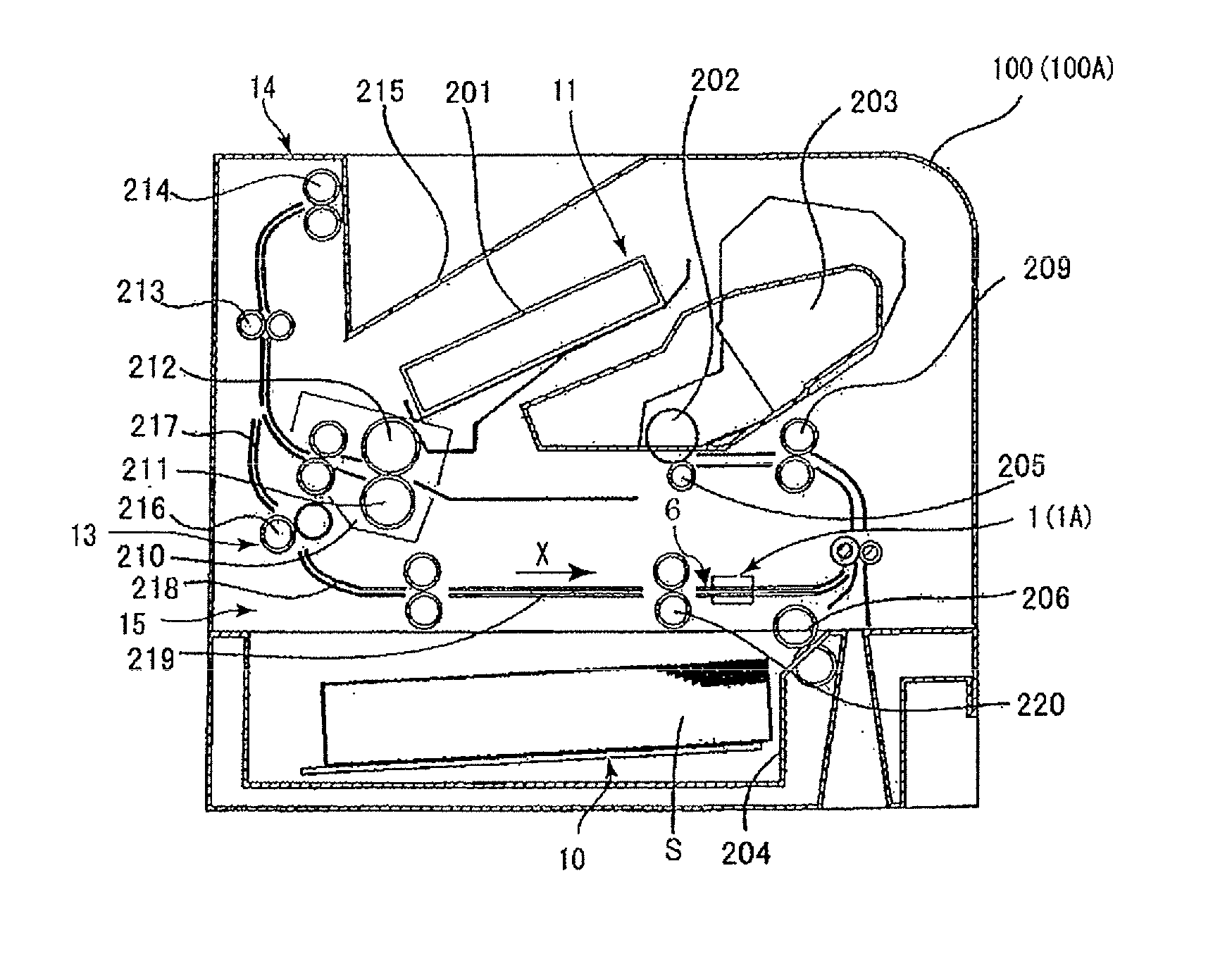
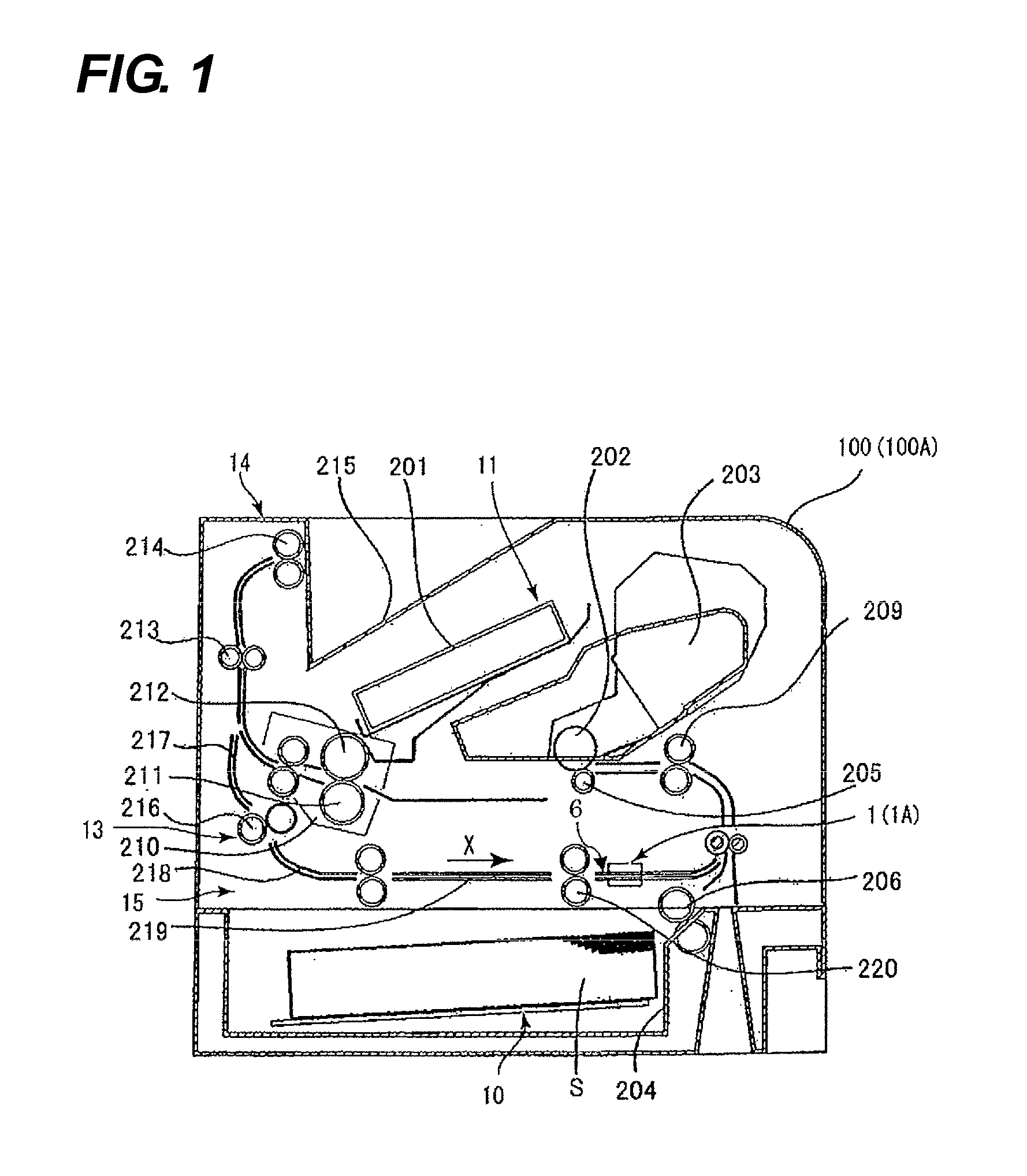
[0026]The laser beam printer 100 according to the first embodiment of the present invention will be described with reference to FIGS. 1 to 4. First, the entire structure of the laser beam printer 100 according to the first embodiment will be described with reference to FIG. 1. FIG. 1 is a sectional view schematically illustrating the entire structure of the laser beam printer 100 according to the first embodiment of the present invention.

[0027]As illustrated in FIG. 1, the laser beam printer 100 has a sheet feeding portion 10 which feeds sheets S, and an image forming portion 11 which forms images on the sheets S fed from the sheet feeding portion 10. Further, the laser beam printer 100 has a fixing portion 210 which fixes images, a discharge portion 14 and a conveying portion 15 which is a sheet conveying apparatus.

[0028]The sheet feeding portion 10 has a sheet cassette 204 which accommodates the sheets S, a pair of feed rollers 206 which feed the sheets S accommodated in the sheet...

second embodiment

[0059]Next, a laser beam printer 100A according to a second embodiment of the present invention will be described with reference to FIGS. 7 to 9 in addition to FIG. 1. FIG. 7 is a perspective view illustrating a sheet end part detecting portion 1A of the laser beam printer 100A according to the second embodiment. FIG. 8 is a partial enlarged view illustrating a sensor unit 8A of the sheet end part detecting portion 1A according to the second embodiment. FIG. 9 is a view for describing an operation range of the sheet end part detecting portion 1A according to the second embodiment.

[0060]The laser beam printer 100A according to the second embodiment differs from the laser beam printer 100 according to the first embodiment in covering light emitting elements 21 by means of cover members 3A. Hence, with the second embodiment, the difference from the first embodiment, that is, light emitting elements 21 covered by the cover members 3A, will be mainly described.

[0061]In addition, with the...


PUM


Abstract

A sheet conveying apparatus which detects an end part position of a sheet in a sheet width direction orthogonal to a conveying direction of the sheet conveyed on a sheet conveying path, comprising a plurality of sensor portions; a holding portion which holds the plurality of sensor portions; a plurality of aperture stops which is disposed between the light emitting portions and the light receiving portions and which is provided on the holding portion; and a driving portion which causes a movement of the holding portion in the sheet width direction.

Description

BACKGROUND OF THE INVENTION[0001]1. Field of the Invention[0002]The present invention relates to a sheet conveying apparatus which has a position detecting apparatus which detects an end part position of a sheet, and an image forming apparatus having this sheet conveying apparatus.[0003]2. Description of the Related Art[0004]A conventional image forming apparatus pulls out sheets on which images are formed, one by one from a sheet cassette by means of feeding rollers to feed to the image forming portion. Therefore, there are cases where sheets to be fed (skewed and fed) are conveyed in an inclined state with respect to a sheet conveying direction due to the difference between outer diameters of feeding rollers or the difference between feeding speeds produced by friction of feeding rollers, or the influence of the sliding resistance between sheets and a conveying guide which conveys sheets.[0005]When sheets are skewed and fed, if, for example, a toner image on a photosensitive drum ...

Claims


Application Information

Patent Timeline
Patent Type & Authority Applications(United States)
IPC IPC(8): G03G15/00B65H5/00B65H7/14
CPCB65H7/10G03G15/6567B65H85/00B65H2511/242B65H2511/514B65H2553/412B65H2553/81B65H2553/822B65H2701/1315G03G15/5029G03G15/55G03G2215/0043G03G2215/00586G03G2215/00616G03G2215/00721B65H7/14G03G15/6564B65H2220/01B65H2220/03B65H2511/24B65H2553/82
Inventor KAIGA, MIHOYAMAMOTO, SHINKICHI
Owner CANON KK
Why Eureka
Try Eureka