Dish antenna

a technology of antenna and parabolic dish, applied in the direction of antennas, electrically short antennas, electrical equipment, etc., can solve the problems of large space occupation, large antenna volume, and unfavorable use, and achieve the effect of reducing space occupation, reducing space occupation, and reducing space occupation

Inactive Publication Date: 2012-01-05
CROWN STAR ASIA PACIFIC
View PDF5 Cites 5 Cited by
  • Summary
  • Abstract
  • Description
  • Claims
  • Application Information

AI Technical Summary

Benefits of technology

The technical effect of this patent is to create a smaller and more efficient dish antenna system with multiple options for varying gains without having to replace or adjust parts. This design allows for easier installation and flexibility while also saving money on space usage compared to traditional systems.

Problems solved by technology

The technical problem addressed in this patent text is the appearance and size of small-sized antennas in the market. These antennas often have a bulky appearance with a large parabolic dish surface that occupies a lot of space. The problem is to create an antenna that is aesthetically pleasing and compact while still providing good signal amplification.

Method used


Image

  • Dish antenna
  • Dish antenna
  • Dish antenna

Examples


Embodiment Construction

[0014]The following descriptions are exemplary embodiments only, and are not intended to limit the scope, applicability or configuration of the invention in any way. Rather, the following description provides a convenient illustration for implementing exemplary embodiments of the invention. Various changes to the described embodiments may be made in the function and arrangement of the elements described without departing from the scope of the invention as set forth in the appended claims.

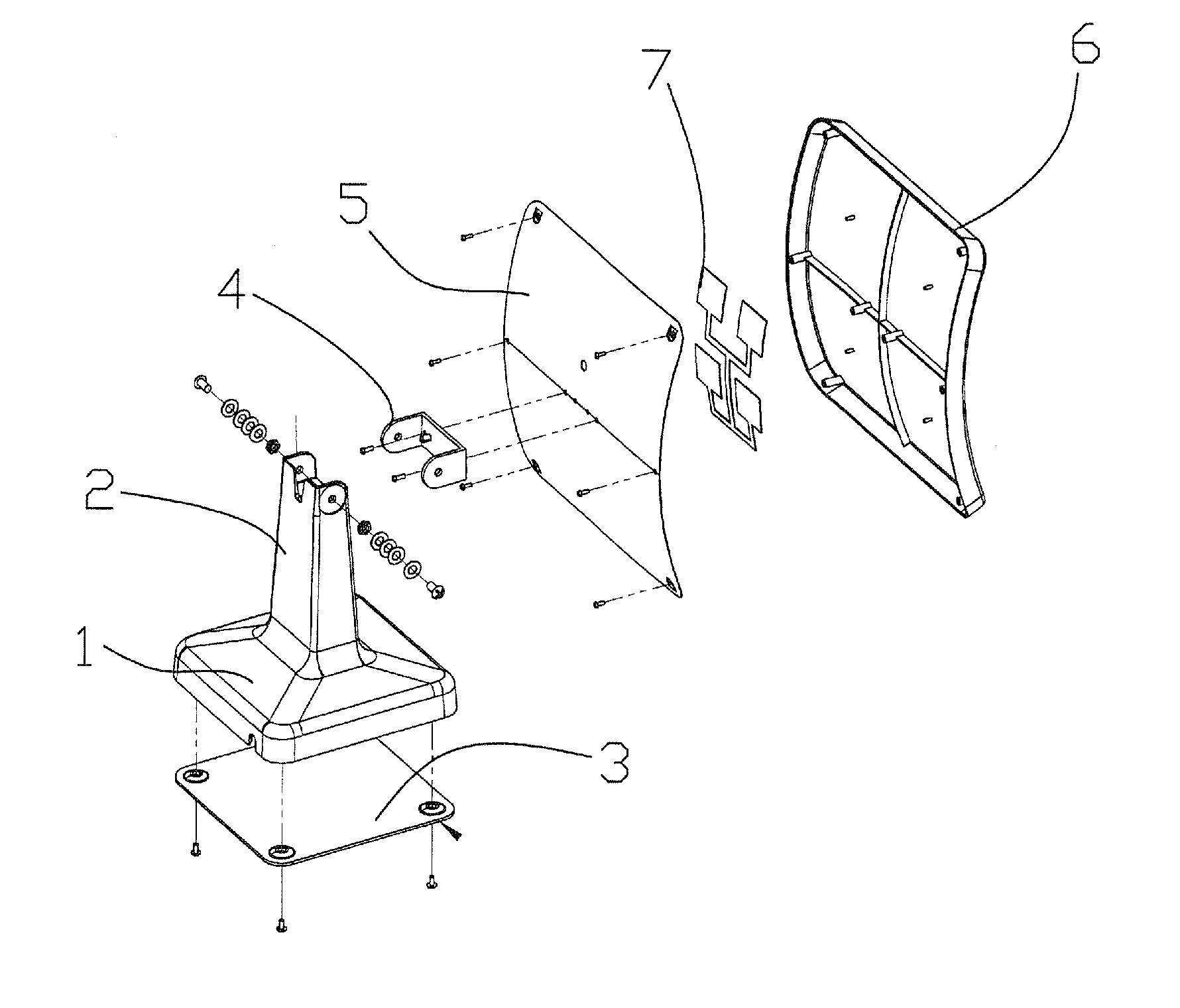
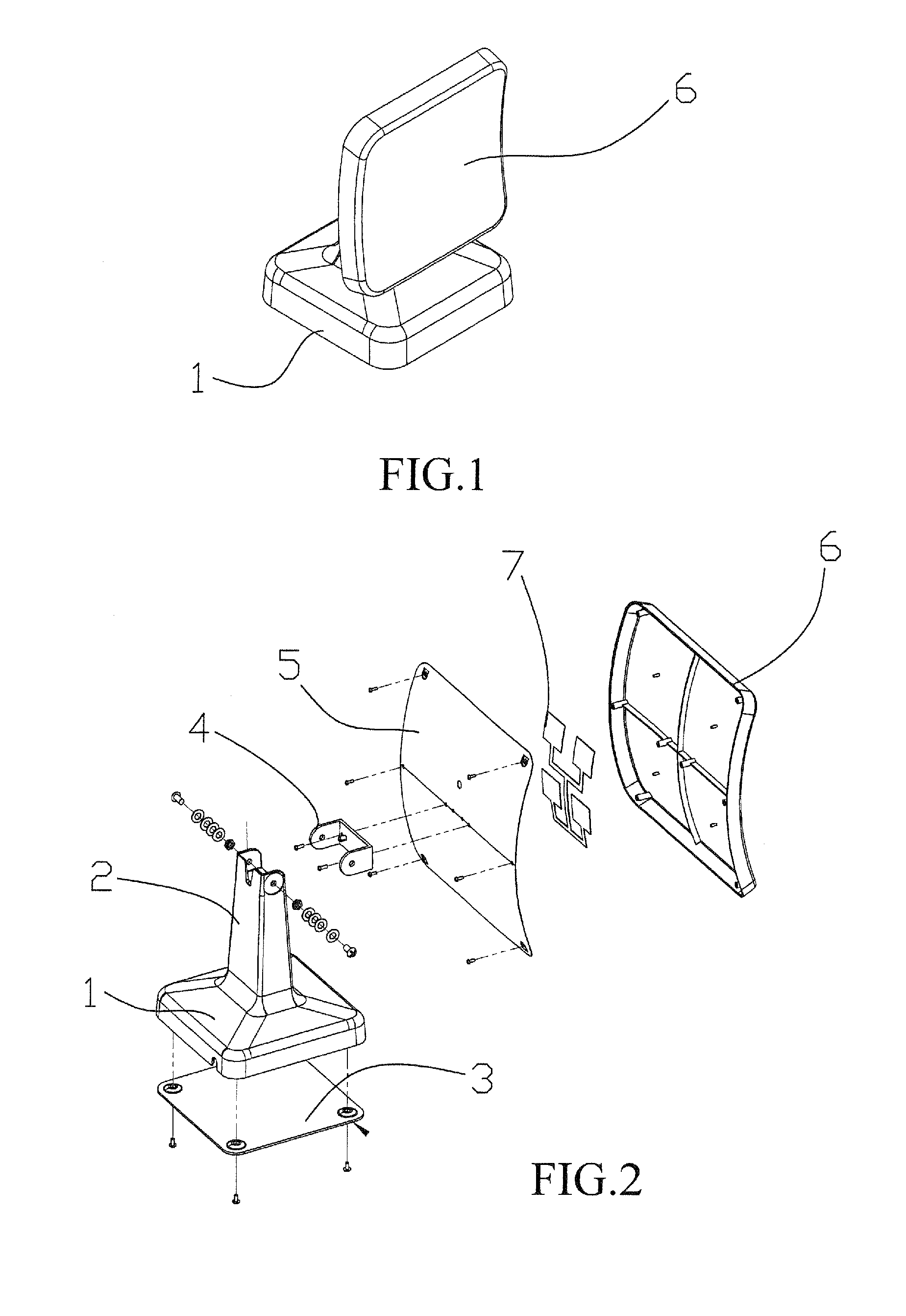
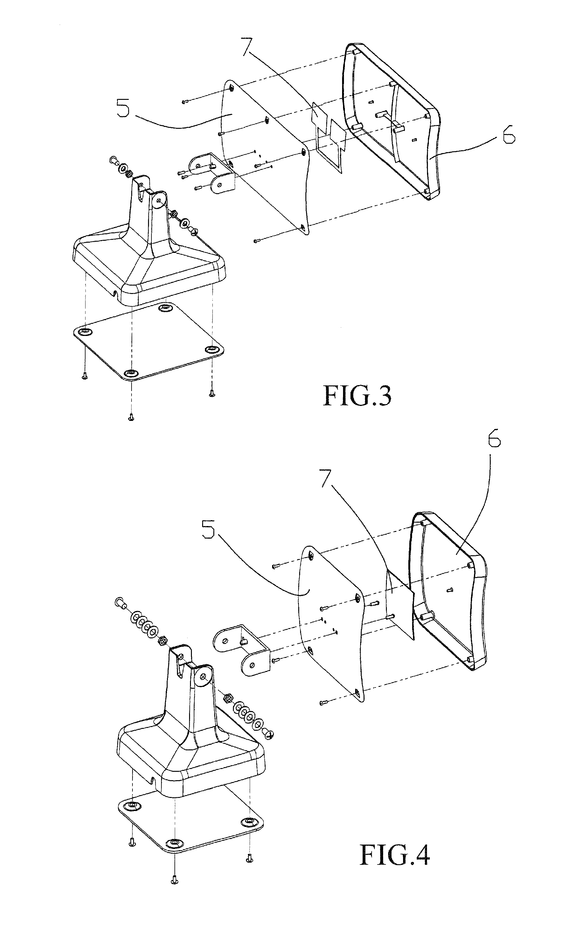
[0015]Embodiments of dish antenna according to the present invention will now be described with reference to the drawings. As shown in FIG. 1, the dish antenna comprises a dish portion 6 that is mounted to a stand or base 1. As shown in FIG. 2, a metal plate 5 is arranged inside the dish portion 6 and is mounted to the stand 1. The dish portion 6 shows a curved configuration. The metal plate 5 carries at least one antenna element 7 mounted thereto. The antenna element 7 is made of nickel silver to p...


PUM


Abstract

A dish antenna is provided as an antenna arrangement that reduces overall size, occupies a small amount of space, and shows an effect of high gain. The dish antenna includes a dish portion, a metal plate, a bracket, a carrier, a stand, and a bottom board. The dish portion shows a curved configuration. The metal plate carries at least one antenna element mounted thereto in a rectangular array, or in a left-right symmetric form, or simply set at a central position. The antenna elements are connected to each other with transmission match lines to realize concentration and in-phase superimposition of electromagnetic waves and increase of transmitting/receiving power of antenna.

Description


Claims


Application Information

Patent Timeline
Owner CROWN STAR ASIA PACIFIC
Why Eureka
Try Eureka