Heat exchanger with welded plates

a technology of heat exchanger and plate, which is applied in the direction of stationary plate conduit assembly, lighting and heating apparatus, station tubular conduit assembly, etc., can solve the problems of degrading the stiffness and mechanical strength of the exchanger, affecting the efficiency of the exchanger, and exposing welds, so as to ensure the rigidity of the plate and ensure the mechanical strength of the assembly

Active Publication Date: 2012-01-05
VITHERM R L
View PDF9 Cites 21 Cited by
  • Summary
  • Abstract
  • Description
  • Claims
  • Application Information

AI Technical Summary

Benefits of technology

[0012]The use of angle irons adapted to receive the edges of the plates makes it possible to improve the assembly and securing together of said plates. In practice, fitting the plates into the openings of the angle irons, which are independent of the rails, is simpler than welding said plates directly to said rails. Furthermore, the assembly constraints are reduced since, in the prior art, the rails have to receive not only the plates, but also the side walls forming the chamber. It is now the angle irons, and no longer the rails, that ensure the segregation of the fluids between the two circuits. Furthermore, the thermal and mechanical stresses are now applied at the level of the openings of the angle irons which can absorb significant expansions and pressures, without damaging the seal-tightness of the assembly. Another advantage resulting from the invention is that the angle irons now provide cladding and protection for the rails, which simplifies the design and improves the rigidity and the mechanical strength of the exchanger.

Problems solved by technology

Furthermore, the welds absorb all the mechanical stresses and significant heat expansions, so that these welds can quickly break and lead to seal-tightness problems (and therefore a drop in the efficiency of the exchanger) between the two fluid circuits.
Furthermore, these welds are exposed directly to the fluids flowing in the appliance.
A second drawback lies in the fact that the plates (20) need to have limited surface areas (in practice, at best 75 cm×75 cm) so that said plates and the side walls (5, 6, 7, 8) of the chamber are not subjected to an excessive pressure which would risk degrading the stiffness and mechanical strength of the exchanger.
Another major drawback lies in the fact that the link between the vertical edges (25, 26, 27, 28) and the rails (3) is subject to significant mechanical stresses and heat expansions, so that these links can quickly break and lead to seal-tightness problems (and therefore a drop in the efficiency of the exchanger) between the two fluid circuits.

Method used


Image

  • Heat exchanger with welded plates
  • Heat exchanger with welded plates
  • Heat exchanger with welded plates

Examples


Embodiment Construction

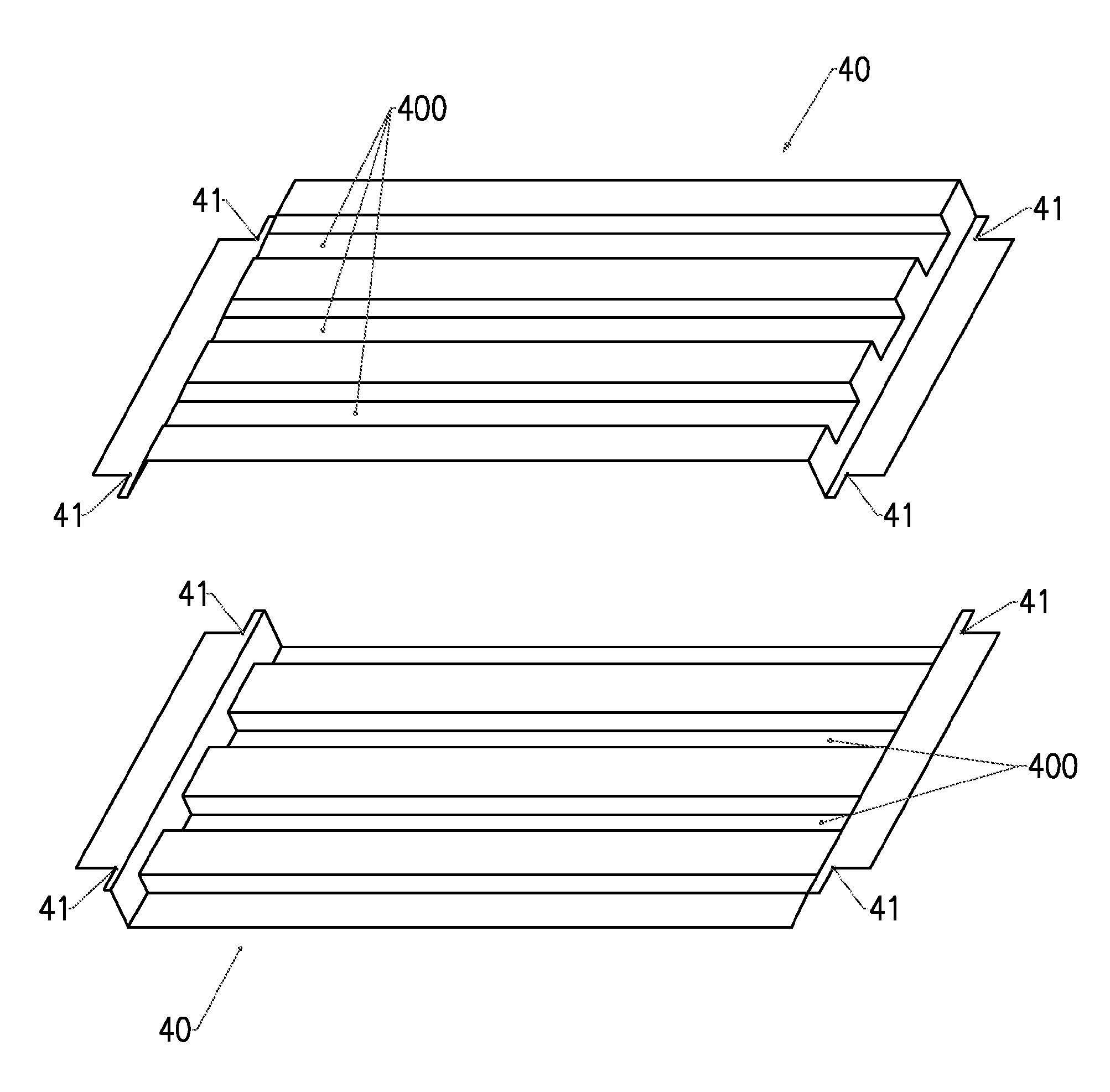
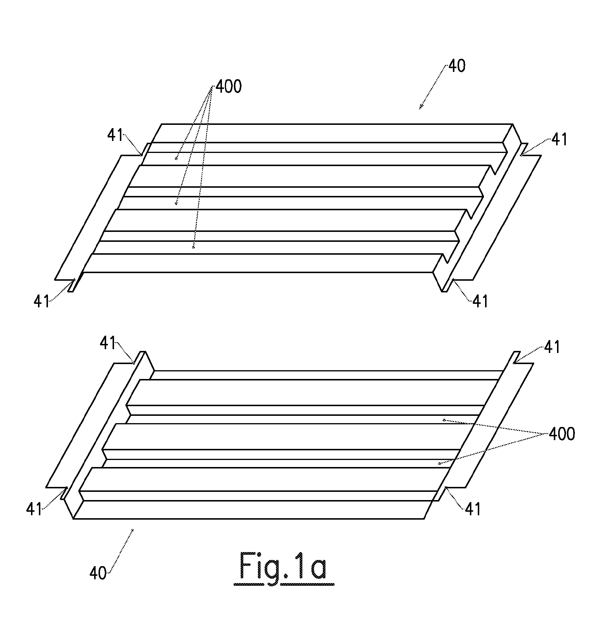
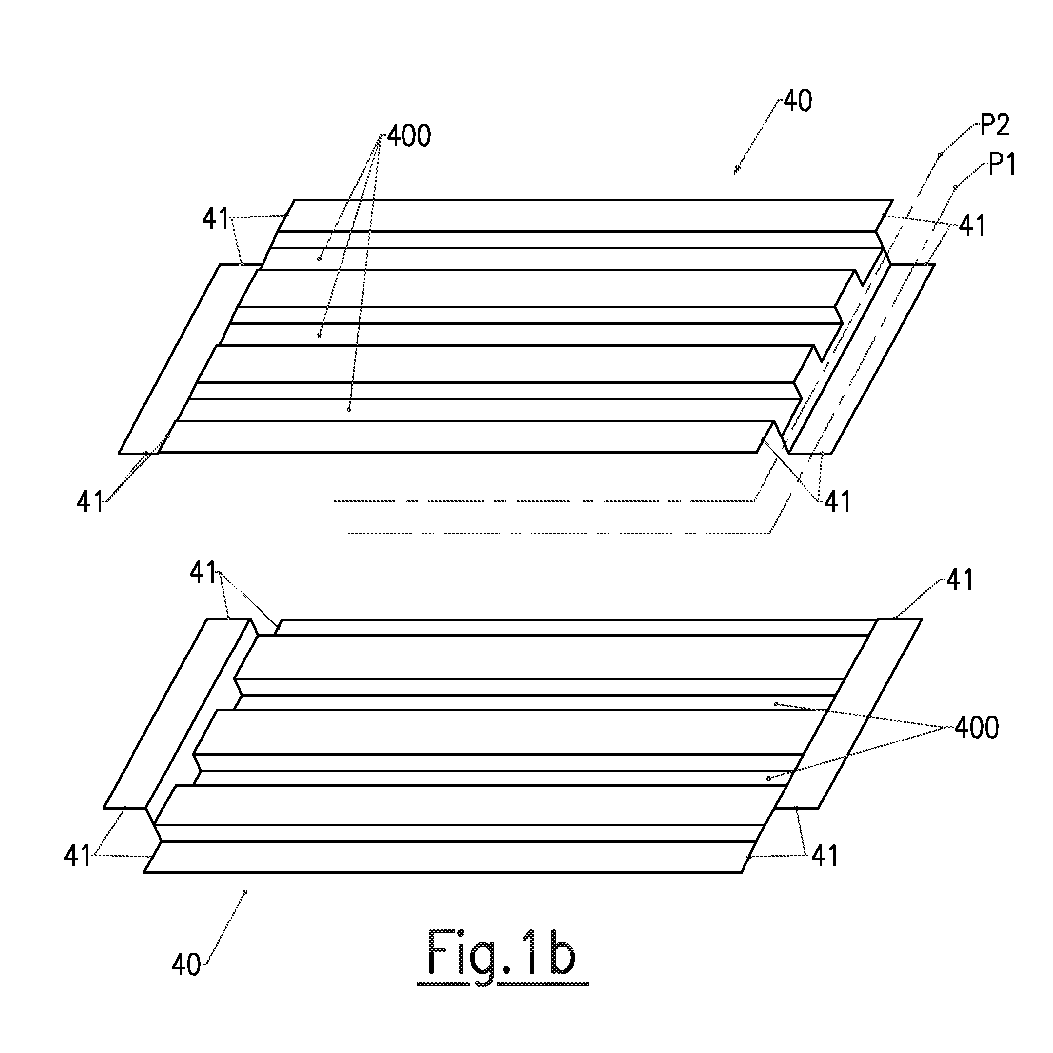
[0027]The heat exchanger that is the subject of the invention is of the type comprising a closed chamber inside which are arranged ribbed plates defining between them interpenetrating independent circuits in which fluids are intended to flow, the side walls delimiting said chamber being fixed to vertical rails. This type of exchanger is of the type known to those skilled in the art.

[0028]Referring to the appended figures and in particular to FIGS. 2, 3, 4, 7 and 8, the exchanger has a general parallelepipedal shape with dimensions mainly dependent on the number of stacked plates and the dimensions thereof. Referring to FIG. 2, this exchanger comprises one (or more) modules 1 of plates 40 juxtaposed in roughly parallelepipedal shape, inserted on four vertical rails 10 arranged at the four corners. The number of modules 1 used is dependent on the flow rate of the fluids to be handled. The rails 10 appear in the form of metal poles, hollow or solid, of substantially rectangular section...


PUM

PropertyMeasurementUnit
lengthaaaaaaaaaa
lengthaaaaaaaaaa
thicknessaaaaaaaaaa

Abstract

The invention relates to a heat exchanger, comprising a closed chamber in which are arranged ribbed welded plates (40) defining therebetween independent and mutually penetrating circuits in which fluids flow, the side walls defining said chamber being attached onto vertical rails, characterised in that said plates comprise at each angle an edge (41) that fits into apertures formed on vertical angle corners (60), said rails being inserted into said corners. The use of angle corners for receiving the edges of the plates improves the assembly and the retention of the plates therebetween.

Description

TECHNICAL FIELD OF THE INVENTION[0001]The subject of the invention is a heat exchanger with welded plates. It also relates to a plate intended to be used in this exchanger.[0002]The invention relates to the technical field of heat exchangers produced by the juxtaposition of plates welded together and defining interpenetrating cold and hot fluid circuits.STATE OF THE ART[0003]Plate heat exchangers are well known to those skilled in the art. These exchangers generally provide for the transfer of cold or heat between a cold fluid and a hot fluid, without said fluids coming into contact. For example, these exchangers can be used to provide for steam condensation by contact with a cold source. Such exchangers are, for example, disclosed in the patent documents WO 93 / 22608 (FERNANDEZ) and FR 2.562.997 (VICARS).[0004]The exchanger described in the document WO 93 / 22608 (FERNANDEZ) comprises (the references between brackets relate to that document) a closed chamber inside which are arranged ...

Claims


Application Information

Patent Timeline
Patent Type & Authority Applications(United States)
IPC IPC(8): F28D7/00B32B3/00
CPCF28D9/0037F28F3/08Y10T428/24479F28F2275/14F28F9/001
Inventor MALUGANI, GERARDCADORET, JEAN-MICHEL
Owner VITHERM R L
Why Eureka
Try Eureka