
Socket structure of miniature light bulb set

a technology of socket structure and light bulb, which is applied in the direction of coupling parts engagement/disengagement, coupling device connection, electrical apparatus, etc., can solve the problems of loss of cord retention function, insufficient structural strength between the base and the socket, etc., and achieve the effect of increasing the thickness of the material

Inactive Publication Date: 2011-12-29
LIN DE HUI
View PDF2 Cites 9 Cited by
  • Summary
  • Abstract
  • Description
  • Claims
  • Application Information

AI Technical Summary

Benefits of technology

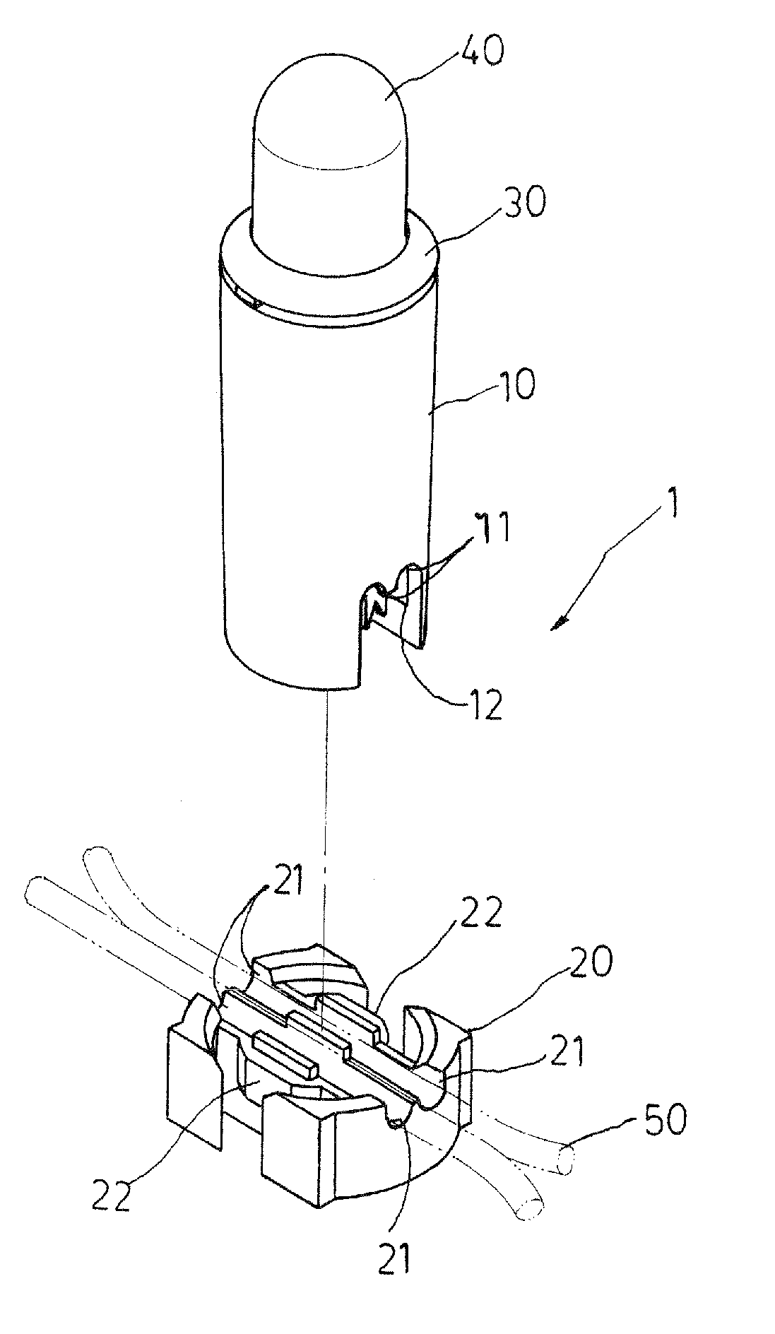
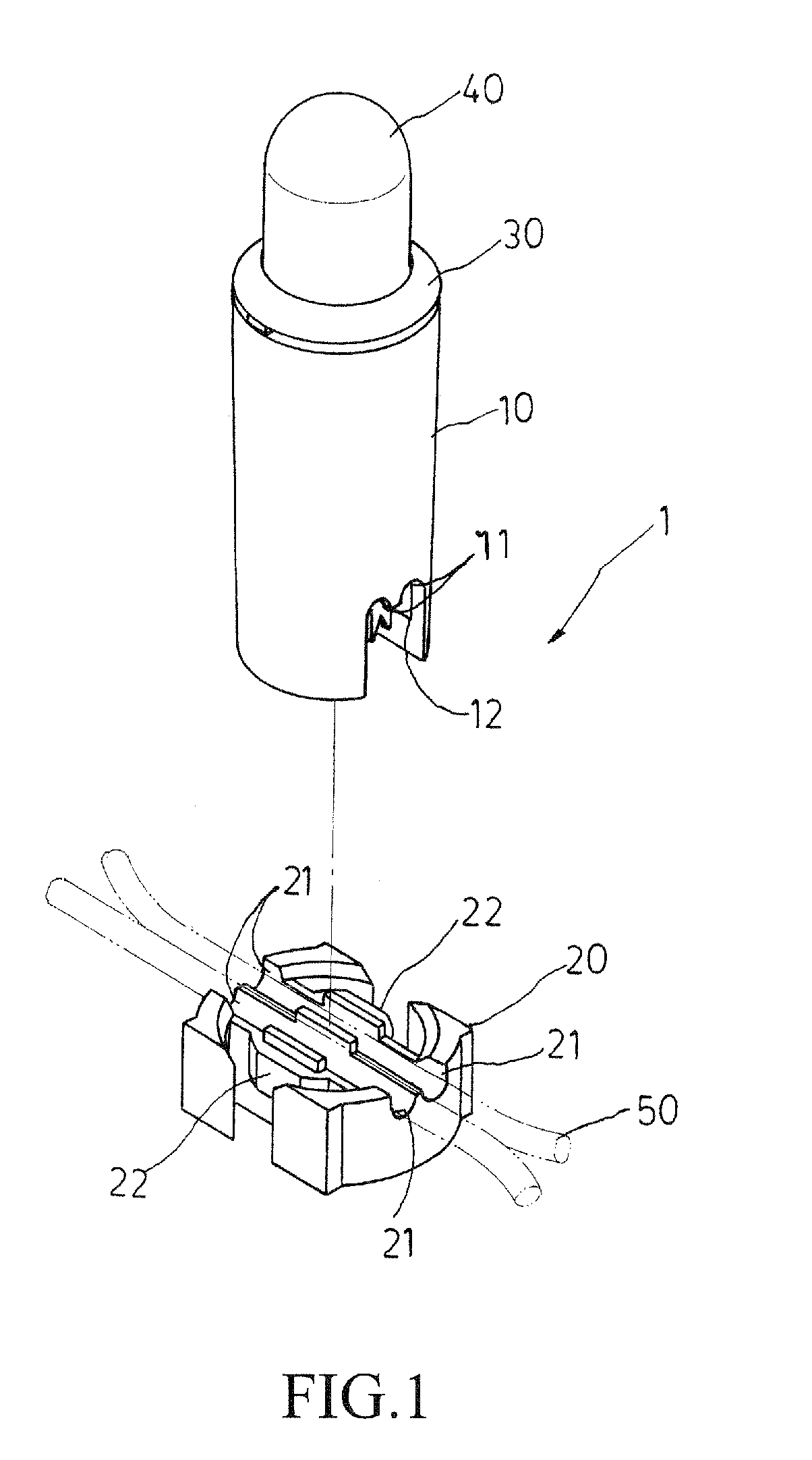
[0003]In view of the problems discussed previously in association with the known miniature light bulb set, the present invention aims to provide a light bulb socket that comprises a structure for securely retaining power cords and a structure for coupling between the socket and a base member. According to the present invention, a socket assembly is provided, comprising a socket body, a base member that receives power cords set thereon, and a holder that receives and holds a light bulb. The improvements made according to the present invention are that the socket body has a bottom portion having front and rear sides forming cord cavities each of which forms a rim to form the structure for positioning and retaining the cord and that the base member has left and right sidewalls each forming a retention block that projects outwards and has an increased thickness of material for forming the structure for coupling with the socket body. As such, the improved structure makes it possible to completely resolve the problems of the conventional miniature bulb socket that the cord retention structure is susceptible to breaking due to stretching of the cord and thus losing the function of cord retention and that the coupling structure between the base and the socket is not structurally strong enough to securely hold the base and the socket together when the power cord is forcibly pulled.

Problems solved by technology

As such, the improved structure makes it possible to completely resolve the problems of the conventional miniature bulb socket that the cord retention structure is susceptible to breaking due to stretching of the cord and thus losing the function of cord retention and that the coupling structure between the base and the socket is not structurally strong enough to securely hold the base and the socket together when the power cord is forcibly pulled.

Method used


Image

  • Socket structure of miniature light bulb set
  • Socket structure of miniature light bulb set
  • Socket structure of miniature light bulb set

Examples


Embodiment Construction

[0010]The following descriptions are exemplary embodiments only, and are not intended to limit the scope, applicability or configuration of the invention in any way. Rather, the following description provides a convenient illustration for implementing exemplary embodiments of the invention. Various changes to the described embodiments may be made in the function and arrangement of the elements described without departing from the scope of the invention as set forth in the appended claims.

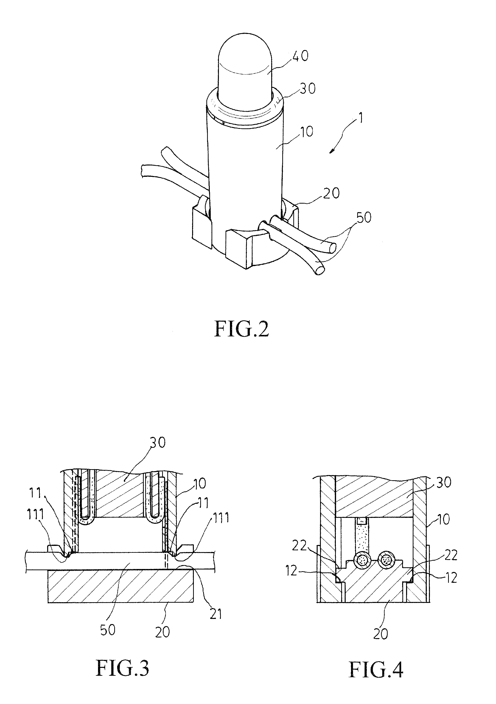
[0011]Referring to FIGS. 1 and 2, a light bulb set according to the present invention comprises a socket assembly (1), which comprises a socket body (10), a base member (20) that receives a power cords (5) set thereon, and a holder (30) that receives and holds a bulb (40). As shown in FIGS. 1 and 3, the socket body (10) has a bottom that has front and rear sides in which cord cavities (11) are formed. Each cord cavity (11) forms a rim (111) extending along a sidewall of the cavity (11). As shown in ...


PUM


Abstract

A socket assembly is provided for a miniature light bulb set, including a socket body, a base member that receives power cords set thereon, and a holder that receives and holds a light bulb. The socket body has a bottom portion having front and rear sides forming cord cavities each of which forms a rim to form the structure for positioning and retaining the cord. The base member has left and right sidewalls each forming a retention block that projects outwards and has an increased thickness of material for forming the structure for coupling with the socket body.

Description

(a) TECHNICAL FIELD OF THE INVENTION[0001]The present invention generally relates to a socket structure for a miniature light bulb set, wherein the socket is improved in respect of a power cord retention structure formed on a bottom of a body of the socket and also an improvement made on a base in respect of a structure for coupling with the socket body.(b) DESCRIPTION OF THE PRIOR ART[0002]The miniature light bulb set to which the improvement is made according to the idea of the present invention is of the type shown in U.S. Pat. No. 6,079,848, which discloses a lamp unit of a light bulb comprising a socket that receives a holder that holds a light bulb therein and a base that carries a power cord thereon. The cord comprises three wires that are arranged in parallel to each other. The base comprises a cord retention structure that is formed of a post located at a central portion of the base. The power cord forms a cutout at a central portion thereof. When the power cord is set on t...

Claims


Application Information

Patent Timeline
Patent Type & Authority Applications(United States)
IPC IPC(8): H01R13/62
CPCH01R4/2404H01R33/09H01R25/14
Inventor LIN, DE-HUI
Owner LIN DE HUI
Learn More