
Locking controller structure of sliding door

a technology of locking controller and sliding door, which is applied in the direction of locking applications, electrical locking circuits, wing accessories, etc., can solve the problems of increasing the number of components, the inability to simply apply the automatic sliding door, and the increase of the manufacturing cost, so as to reduce the number of link members, reduce the components and manufacturing costs, and improve the effect of productivity

Inactive Publication Date: 2011-12-29
HYUNDAI MOTOR CO LTD
View PDF26 Cites 6 Cited by
  • Summary
  • Abstract
  • Description
  • Claims
  • Application Information

AI Technical Summary

Benefits of technology

[0012]Various aspects of the present invention are directed to provide a locking controller mechanism of a sliding door, which can realize reduction of components and manufacturing costs by making it possible to perform a sliding door function particularly with minimum components.
[0016]With the above-described construction, the locking controller mechanism of a sliding door according to the present invention can reduce components and manufacturing costs through reduction of additional link members for the sliding door and improve the productivity through reduction of the weight of the components.

Problems solved by technology

However, since the sliding door as described above in the related art has been developed based on the structure that is operated by the manipulation of a manual handle, it is not suitable to simply apply the automatic sliding door by the switch manipulation to the structure.
Also, since many kinds of link members such as the control lever and the like are used, the number of components is increased and the manufacturing cost is heightened.

Method used


Image

  • Locking controller structure of sliding door
  • Locking controller structure of sliding door
  • Locking controller structure of sliding door

Examples


Embodiment Construction

[0025]Reference will now be made in detail to various embodiments of the present invention(s), examples of which are illustrated in the accompanying drawings and described below. While the invention(s) will be described in conjunction with exemplary embodiments, it will be understood that present description is not intended to limit the invention(s) to those exemplary embodiments. On the contrary, the invention(s) is / are intended to cover not only the exemplary embodiments, but also various alternatives, modifications, equivalents and other embodiments, which may be included within the spirit and scope of the invention as defined by the appended claims.

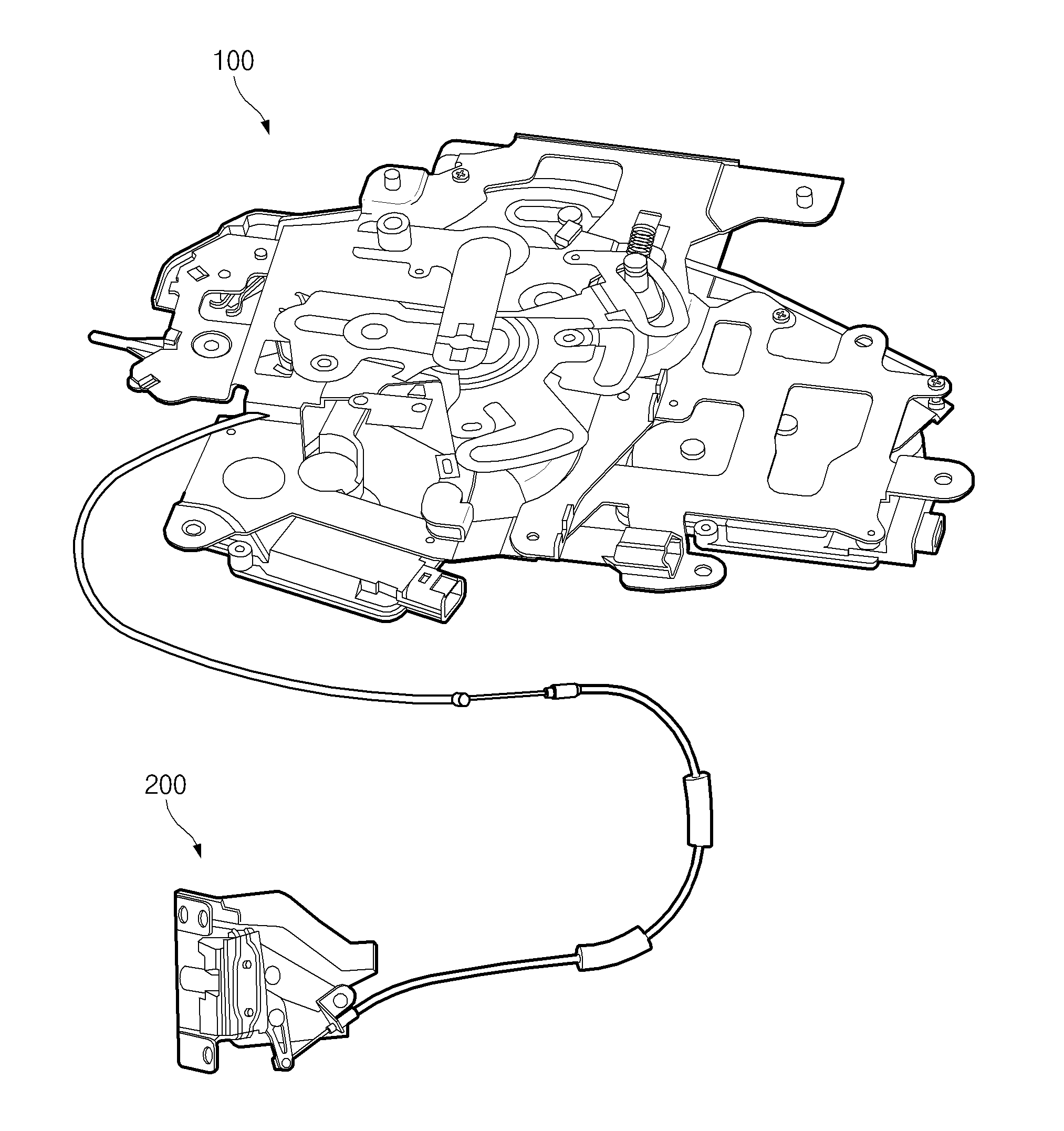
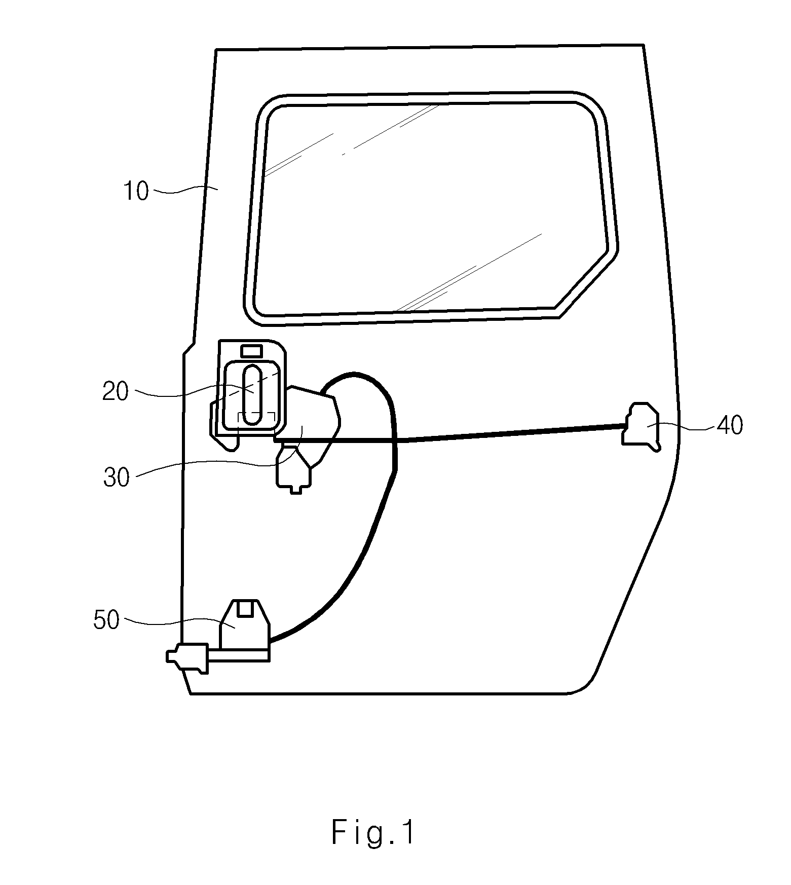
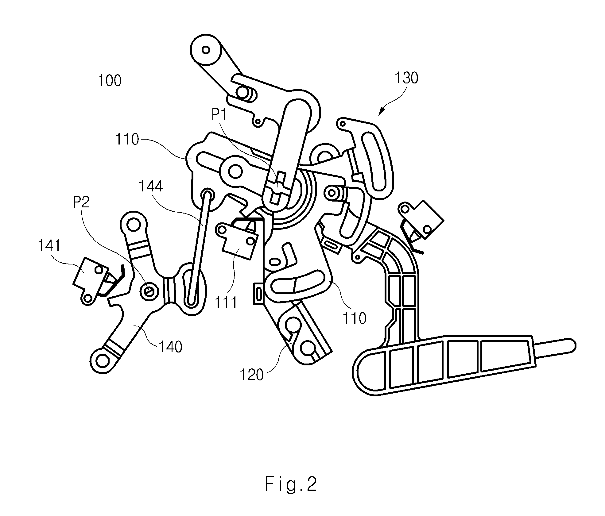
[0026]FIGS. 2 to 5 show a locking controller mechanism of a sliding door according to an exemplary embodiment of the present invention. FIG. 2 is a view illustrating a locking controller mechanism in a locking controller mechanism of a sliding door according to an exemplary embodiment of the present invention, and FIG. 3 is a view ill...


PUM


Abstract

A locking controller mechanism that is capable of opening or closing a sliding door mounted on a vehicle and controlling opening or closing operation of the sliding door through an electrical control unit (ECU), may include an outside lever rotatably mounted about a first pivot shaft and connected to an outside handle that enables the door to be opened or closed on the outside of a vehicle body, a latch release lever rotatably mounted to the first pivot shaft and connected to the outside lever to control latch cables, an inside lever rotatably mounted to the first pivot shaft and connected to the outside lever and an inside handle that enables the door to be opened or closed on the inside of the vehicle body, and a hold open lever rotatably mounted to a second pivot shaft and pivotally connected to the outside lever to be rotatable when the door is closed.

Description

CROSS-REFERENCE TO RELATED APPLICATION[0001]The present application claims priority to Korean Patent Application No. 10-2010-0061447, filed on Jun. 28, 2010 in the Korean Intellectual Property Office, the entire contents of which is incorporated herein for all purposes by this reference.BACKGROUND OF THE INVENTION[0002]1. Field of the Invention[0003]The present invention relates to a locking controller mechanism of a sliding door, and more particularly, to a locking controller mechanism of a sliding door, which can realize reduction of components and manufacturing costs by making it possible to perform a sliding door function with minimum components.[0004]2. Description of the Prior Art[0005]In general, a sliding door provided in a van-type vehicle or the like is adapted to be opened or closed as it slides in forward and backward directions of a vehicle body along a side surface of a vehicle body, and thus has the advantages that a passenger's entrance / exit through the sliding door ...

Claims


Application Information

Patent Timeline
Patent Type & Authority Applications(United States)
IPC IPC(8): E05F15/18E05F15/60
CPCE05B81/64E05Y2900/531E05Y2201/22E05B83/40
Inventor CHOI, JAE HONG
Owner HYUNDAI MOTOR CO LTD
Learn More