Multi-Function Anti-Rotational/Anti-Theft Hitch Ball Assembly
a hitch ball and multi-functional technology, applied in the direction of towed devices, vehicle components, transportation and packaging, etc., can solve the problems of increased manufacturing costs for custom-made hitch balls, interlocking mating surfaces, and increased costs for manufacturers and consumers, and achieves high-efficiency and convenient, inexpensive, and facilitate the fastening of other hitch accessories.
- Summary
- Abstract
- Description
- Claims
- Application Information
AI Technical Summary
Benefits of technology
Problems solved by technology
Method used
Image
Examples
first embodiment
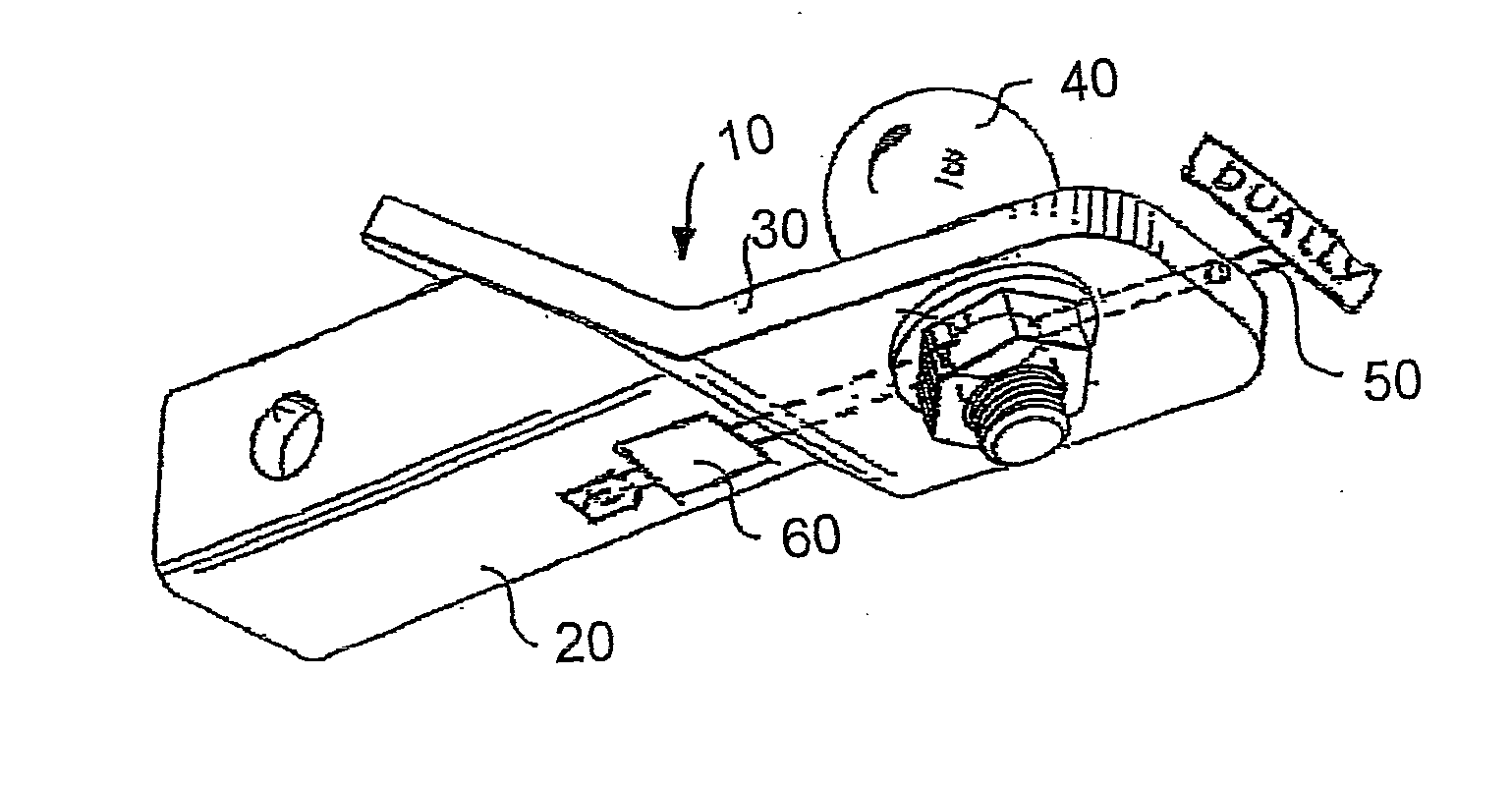
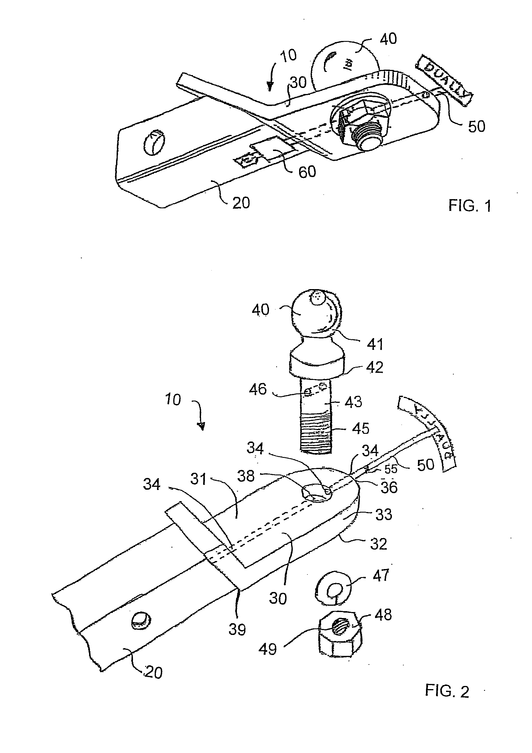
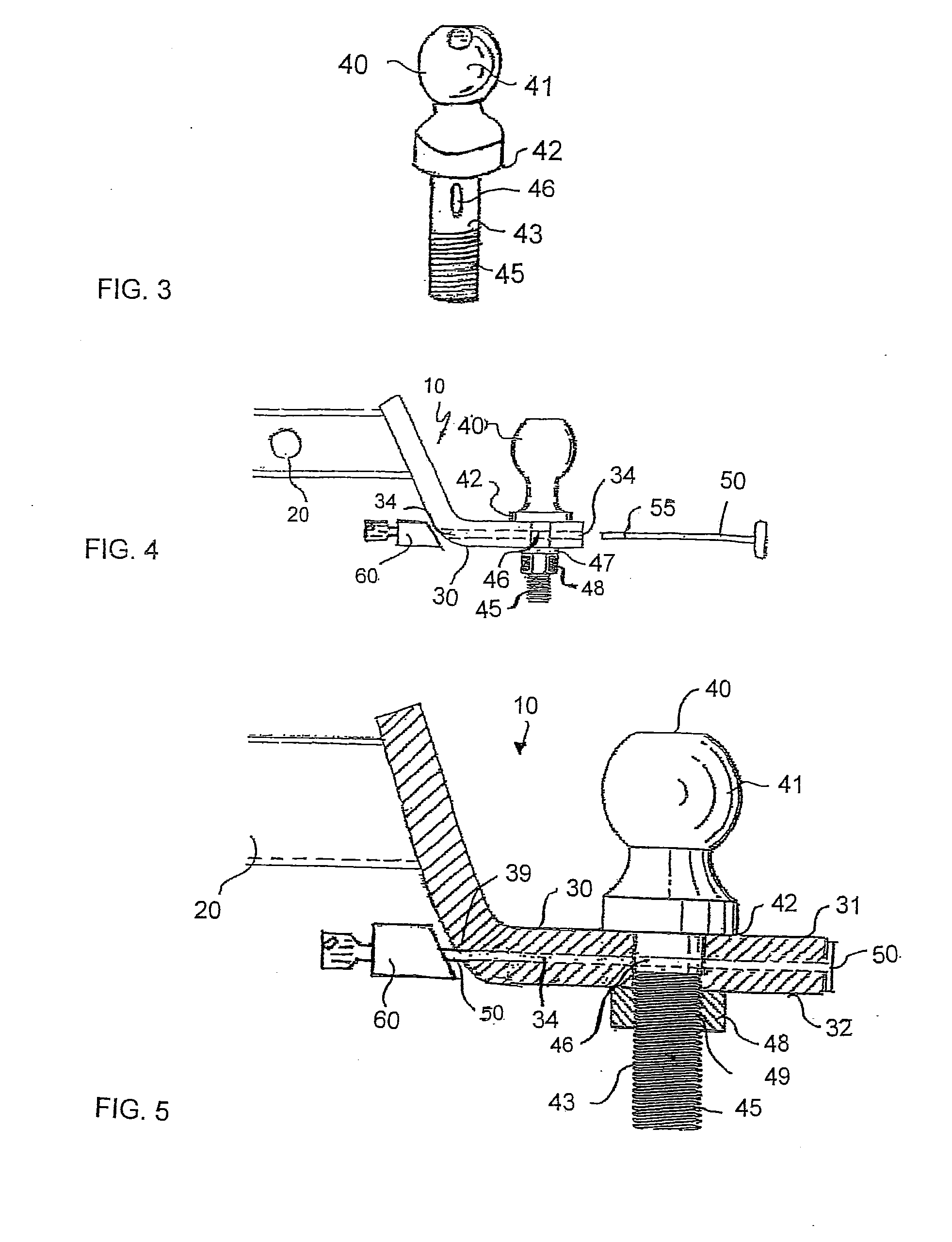
[0048]Referring to FIG. 1, there is shown a bottom rear side perspective view of the inventive Multi-Function Anti-Rotational / Anti-Theft Hitch Ball Assembly referred to by the reference number 10. The assembly performs the function of a standard ball mount and hitch ball and includes an anti-rotational mechanism for interlocking the hitch ball with the ball mount as well as an anti-theft mechanism for preventing unauthorized removal of the hitch ball. The assembly includes a ball mount shank 20, ball mount platform 30, hitch ball 40, locking pin 50 and lock 60. Locking pin 50 may be a stand-alone pin, or an integral feature of an additional accessory such as the shank of an indicia plate, as shown, or shank of other accessories such as reflectors, tail lights, brake lights, or other hitch accessories. When hitch ball 40 is installed on ball mount platform 30 and locking pin 50 inserted into position, lock 60 engages locking pin 50 resulting in anti-rotational and anti-theft hitch ba...
second embodiment
[0052]Referring to FIGS. 6, 7 and 8 there is shown a perspective view, side elevation view and exploded side elevation view of the present invention referred to by Reference Number 100. This embodiment is similar to the embodiment of Reference Number 10 as described above but utilizes a shorter locking pin 50 and an alternate locking mechanism.
[0053]In the illustrated embodiment, throughbore 34 in ball mount platform 30 extends horizontally from the center rear face of the ball mount platform 36, passing through the center of vertical throughbore 38, but does not project through the center forward face of the ball mount platform 39 underneath ball mount shank 20 as in the first embodiment. In this embodiment, throughbore 34 in ball mount platform 30 extends horizontally from the center rear face of the ball mount platform 36, passing through the center of vertical throughbore 38, but stops at a distance between vertical throughbore 38 and forward face of ball mount platform 39.
[0054...
PUM
 Abstract
Description
Claims
Application Information
 - R&D
- Intellectual Property
- Life Sciences
- Materials
- Tech Scout
- Unparalleled Data Quality
- Higher Quality Content
- 60% Fewer Hallucinations
Browse by: Latest US Patents, China's latest patents, Technical Efficacy Thesaurus, Application Domain, Technology Topic, Popular Technical Reports.
© 2025 PatSnap. All rights reserved.Legal|Privacy policy|Modern Slavery Act Transparency Statement|Sitemap|About US| Contact US: help@patsnap.com


