
Sash for sliding door or window

a sliding door or window and sash technology, applied in the direction of door/window fittings, wing suspension devices, wing accessories, etc., can solve the problems of not being able to meet the needs of passengers, not having a significant overall weight, and not having a good appearance. , to achieve the effect of keeping the thermal seal coefficient of the sash high

Inactive Publication Date: 2011-12-22
GO TECH SRL
View PDF13 Cites 11 Cited by
  • Summary
  • Abstract
  • Description
  • Claims
  • Application Information

AI Technical Summary

Benefits of technology

[0019]This invention therefore has for an aim to overcome these disadvantages by providing a sash for sliding doors or windows that is extremely rational, has reduced overall weight, with improved thermal performance, lower production costs, but that is still as reliable and secure as a conventional sash.
[0021]Yet another aim is to obtain a sash that is easy to assemble and has structural continuity as regards both the seal and the maneuverability of the control and sliding elements, such as carriages in lift and slide sashes.
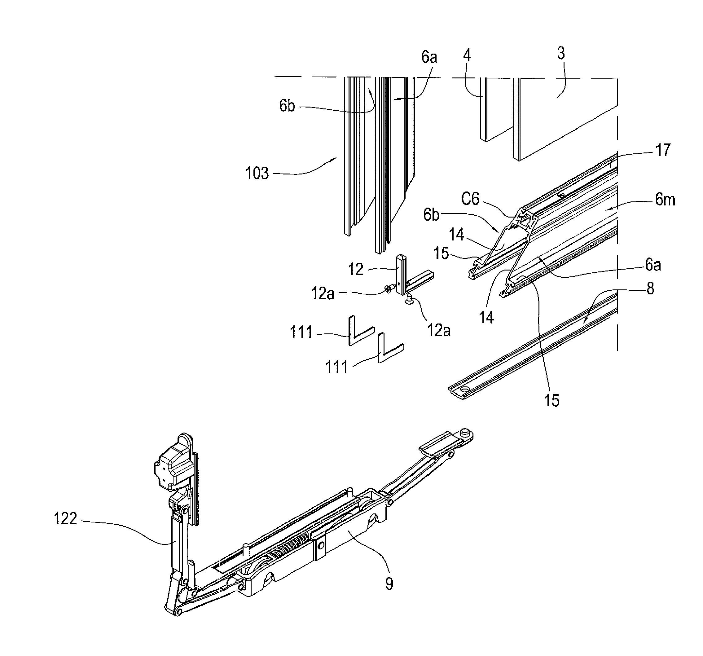
[0030]In this way, “hidden” housing can be obtained for the carriages, without changing the outer appearance of the sash, connecting the carriages to the main operating elements, by means of the rod, to perform the coordinated opening and closing operating movements if necessary (for example, in doors or windows of the “lift and slide” type).
[0034]Advantageously, the angled element may be associated in the profile by housing it in a tubular housing present in the first sealing element: in this way the dimensions are reduced and the contact surfaces between the metal elements are interrupted, thus keeping the sash thermal seal coefficient high.

Problems solved by technology

Therefore, a sash structured in this way may not just have a significant overall weight, but also an appearance that is not always acceptable due to the presence of the visible outer frame (depending on the rooms where it is installed) and high production costs, in particular due to the machining necessary for application of accessory elements which are essential for its movement and closing.

Method used


Image

  • Sash for sliding door or window
  • Sash for sliding door or window
  • Sash for sliding door or window

Examples


Embodiment Construction

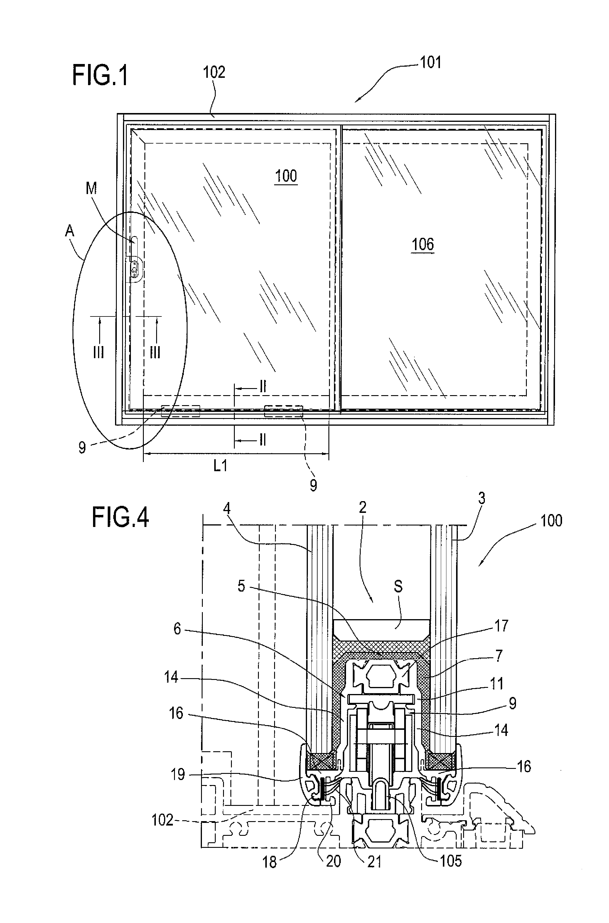
[0051]With reference to the accompanying drawings, and in particular FIG. 1, the sash according to the invention, labelled 100 in its entirety, may be used for sliding doors, windows or French windows.

[0052]This door or window, labelled 101, may comprise, for example, a fixed frame 102, at least one mobile frame or sash 100, one or a pair of carriages 9 and at least one control element M (a handle described in more detail below).

[0053]More specifically, the sash 100 is slidable relative to the fixed frame 102 between a closed position (see FIG. 1) and an open position (not illustrated).

[0054]In more detail, the sash 100 is slidable horizontally along a fixed track 105 positioned at the base of the fixed frame 101 and, in its fully open position (not illustrated), can (purely by way of example) be superposed over a fixed sash 106 or a sash that is also mobile, opening in the opposite direction to the first sash.

[0055]FIG. 1 schematically illustrates, again by way of example and witho...


PUM


Abstract

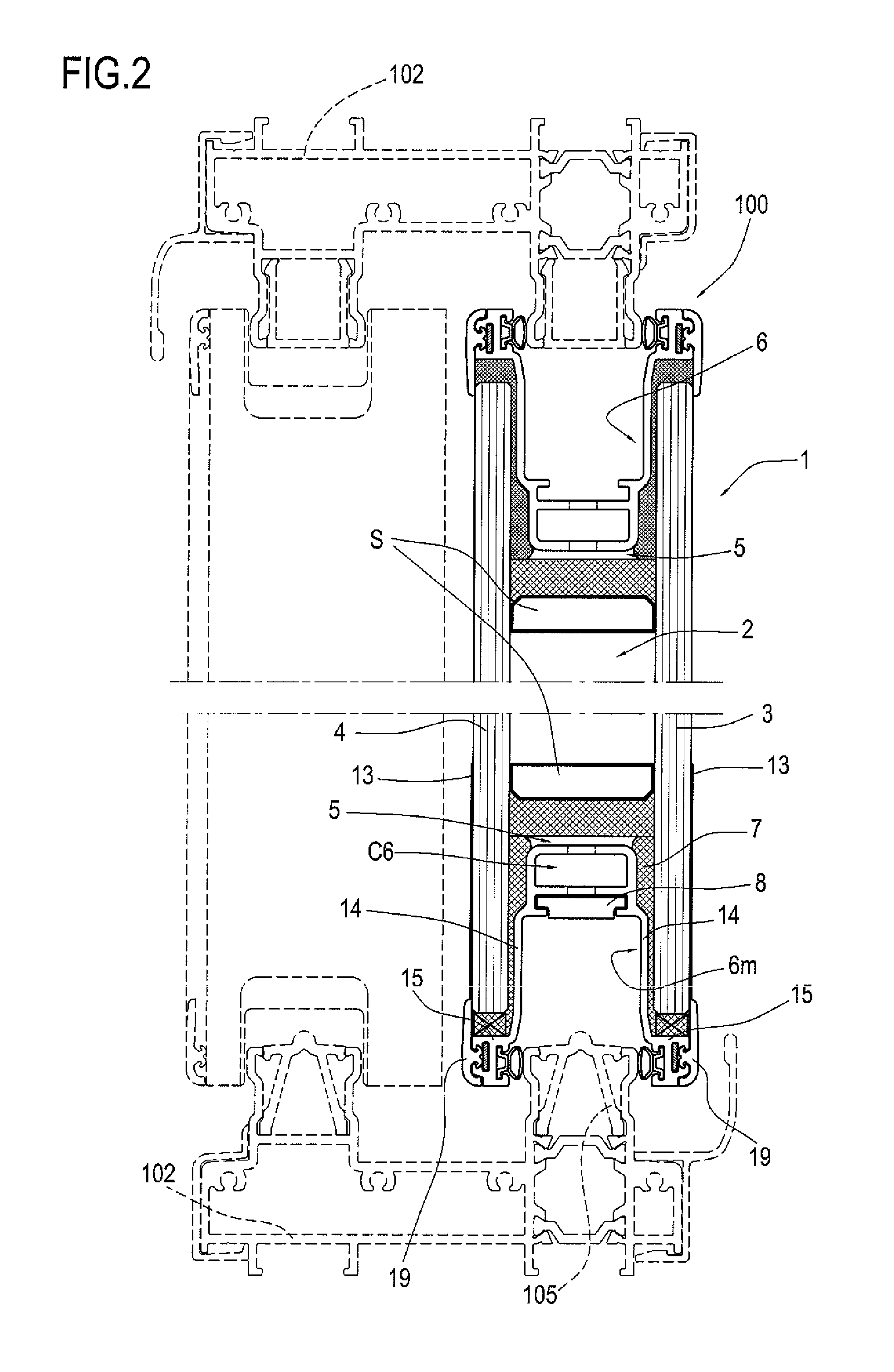
A sash for sliding doors or windows comprises: a main body (1) comprising an insulating chamber (2) obtained from respective glazing panels (3, 4) whose dimensions are larger than the dimensions of the chamber (2), so as to form a perimetric housing (5) which is open towards the outside; a rigid profile (6) forming a frame inside the main body (1) for each side of the main body (1) and designed to be stably accommodated in each housing (5); the rigid profile (6) forming a zone, open to the outside, equipped with accessories and in which means (8, 9, 10) for operating and / or driving the main body (1) in use are housed and / or are slidable; the three rigid profiles (6) each forming a channel (11) accommodating a rod (8) for operating the main means (9) and the accessory means (10) which drive and / or open and close the sash (100); each of the three rigid profiles (6) forming one upright (103) and two crosspieces (6m, 105) of the sash (100), the contiguous ends being shaped so that they are angled, in such a way that they can be joined and form a continuous cover for the corner of the frame; the ends of the profiles (6) are joined by an angled element (12) associated with the corresponding innermost surfaces of the contiguous profiles (6), so that the channel (11) runs uninterruptedly along the three sides.

Description

TECHNICAL FIELD[0001]This invention relates to a sash for a sliding door or window, in particular a sash which can slide on at least one track between an open position and a closed position.BACKGROUND ART[0002]Sliding doors and windows of the traditional or lift and slide type are well known, and basically comprise:[0003]a fixed frame;[0004]at least one mobile frame or sash which slides horizontally, opening and closing relative to the fixed frame;[0005]at least one sliding unit or carriage associated with the bottom crosspiece of the sash and resting on a horizontal base track and designed to enable the sash to slide in both directions;[0006]a control element located on the mobile frame and designed to actuate operating means which can be used to move closing means and to disengage the sash from the fixed frame so that it can be slid open, and, vice versa, when the upright of the sash is in contact with the upright of the fixed frame to stop the sash in a closed positioned;[0007]th...

Claims


Application Information

Patent Timeline
IPC IPC(8): E05D15/12
CPCE06B3/025E06B3/9641E06B3/9616E06B3/4681
Inventor LAMBERTINI, MARCO
Owner GO TECH SRL
Learn More