
Shockwave valvuloplasty catheter system

a valvuloplasty and catheter technology, applied in the field of shockwave valvuloplasty catheter system, can solve the problems of narrowing at the opening of the aortic valve, heart murmur, and impairing the blood flow through the valv

Active Publication Date: 2011-12-01
SHOCKWAVE MEDICAL
View PDF13 Cites 76 Cited by
  • Summary
  • Abstract
  • Description
  • Claims
  • Application Information

AI Technical Summary

Benefits of technology

The patent describes a valvuloplasty system and method for treating a valve with a balloon and a shock wave generator. The balloon is placed adjacent to the valve leaflets or within the valve annulus and inflated with a liquid. The shock waves generated within the balloon impinge upon the valve leaflets and the valve annulus to improve valve function. The system may include an elongated carrier and a balloon carried by the carrier, with at least one pair of coaxially arranged electrodes within the balloon that form a mechanical shock wave. The method may involve placing the balloon on opposite sides of the valve leaflets or within the valve annulus. The technical effects of the invention include improved valve function and reduced risk of complications during valvuloplasty procedures.

Problems solved by technology

This often results in a heart murmur, which can easily be heard with a stethoscope over the heart.
In some cases, though, the calcium deposits thicken and cause narrowing at the opening of the aortic valve.
This impairs blood flow through the valve, causing chest pain or a heart attack.
Unfortunately, most of these valves narrow over a six to 18 month period.

Method used


Image

  • Shockwave valvuloplasty catheter system
  • Shockwave valvuloplasty catheter system
  • Shockwave valvuloplasty catheter system

Examples


Embodiment Construction

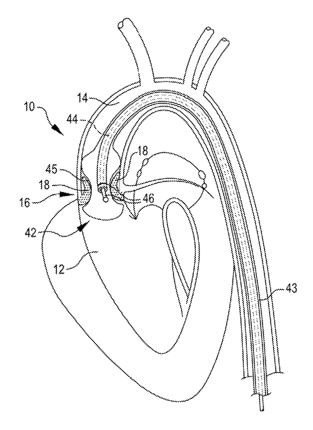
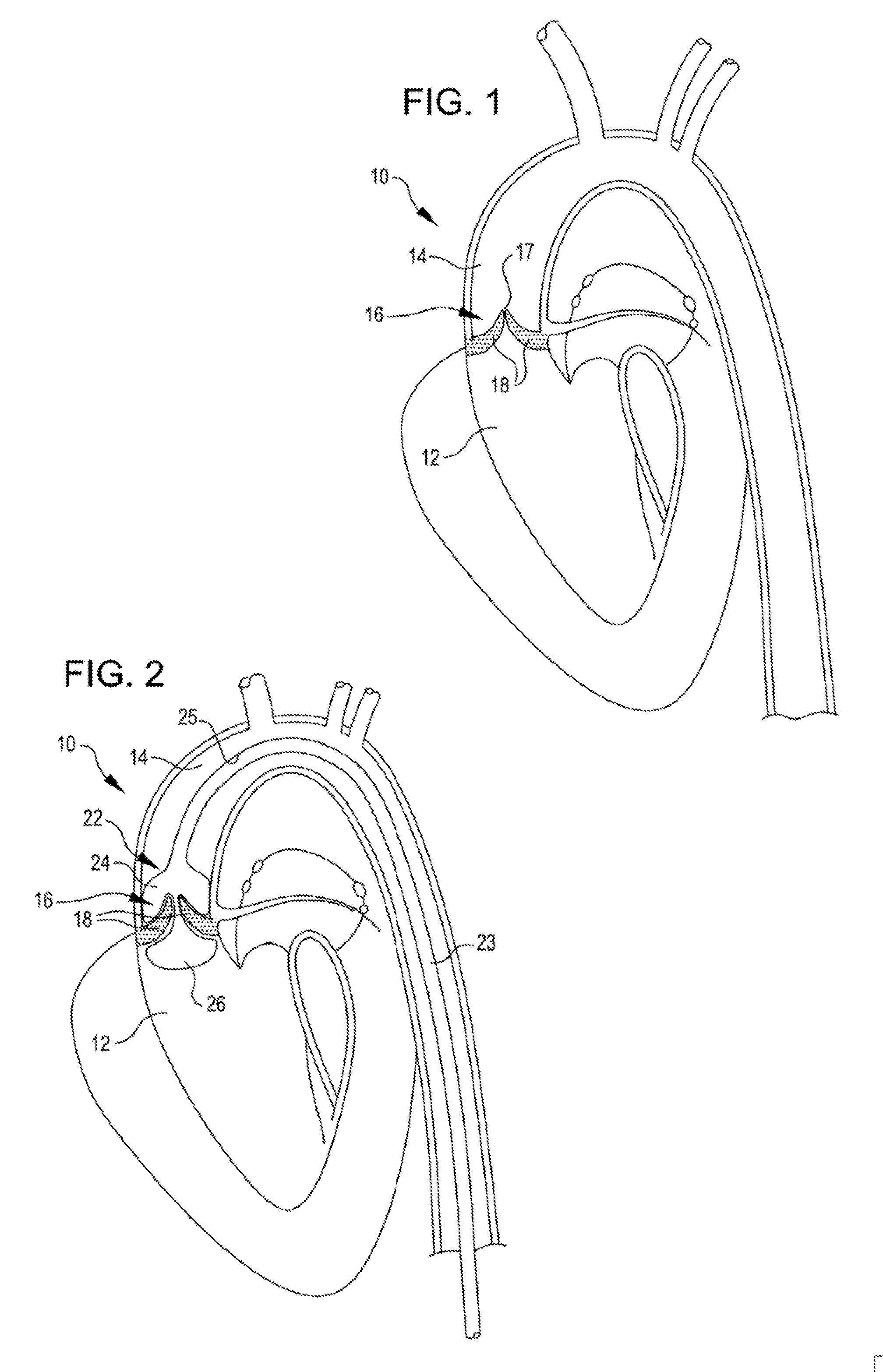
[0026]Referring now to FIG. 1, it is a cut away view of the left ventricle 12, the aorta 14, and the aortic valve 16 of a heart 10 with a stenotic and calcified aortic valve 16. Here more particularly, it may be seen that the opening 17 of the stenotic and calcified aortic valve 16 is restricted in size and that the valve leaflets 18 are thickened with calcium deposits and fibrotic tissue. The thickened leaflets 18 and smaller valve opening 17 restrict blood flow from the heart creating excess work for the heart 10 and poor cardiac output. As previously mentioned, current treatment includes replacement of the valve or attempts too stretch the valve annulus with a balloon.

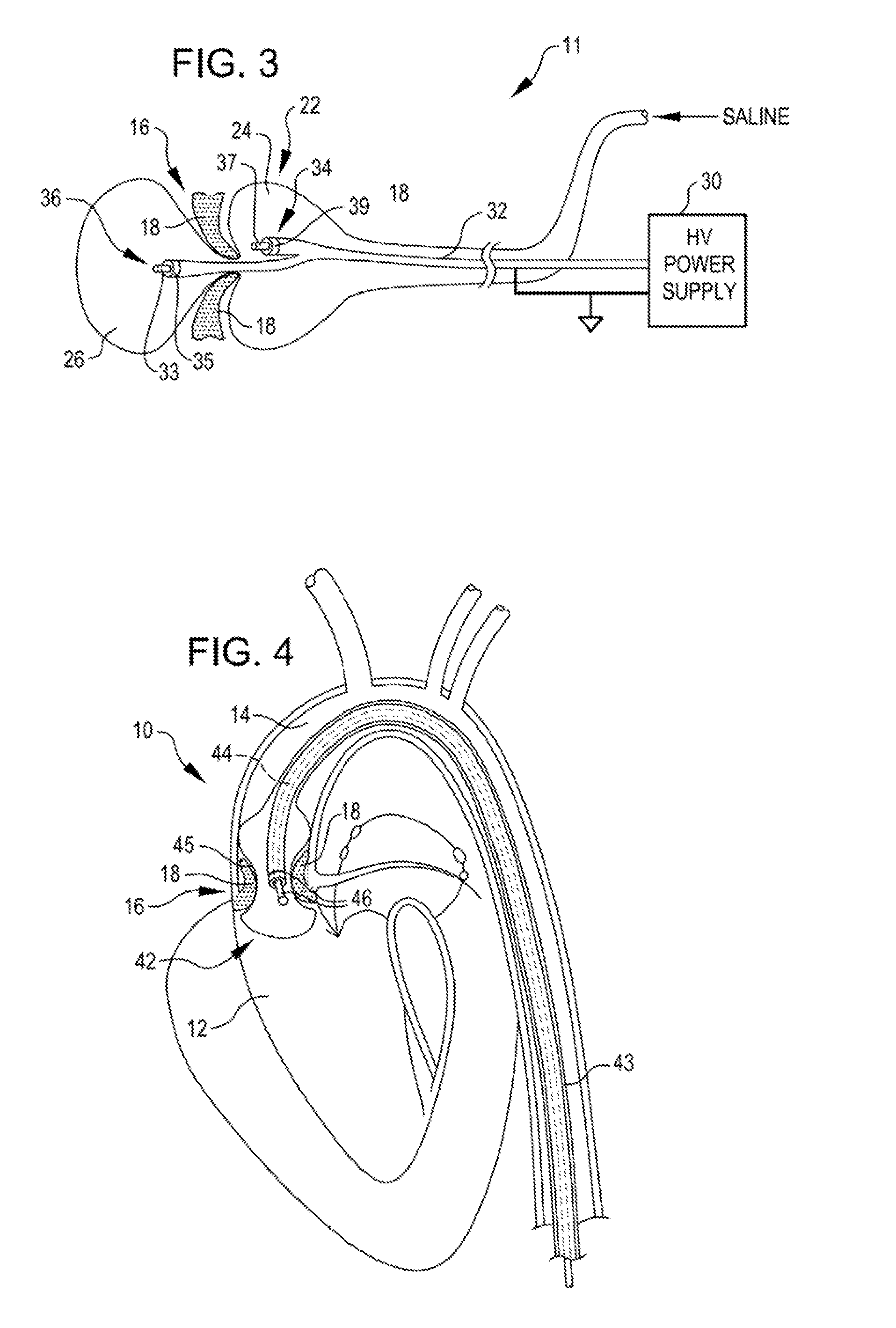
[0027]FIG. 2 is a cut away view of the aortic valve 16 with a treatment balloon 22 placed on both sides of the aortic valve leaflets 18. The balloon 22 may be formed from a compliant or a non-compliant material. The balloon, as seen in FIG. 2, is at the distal end of an elongated tube 23. The treatment balloon 22 ha...


PUM


Abstract

A valvuloplasty system comprises a balloon adapted to be placed adjacent leaflets of a valve. The balloon is inflatable with a liquid. The system further includes a shock wave generator within the balloon that produces shock waves. The shock waves propagate through the liquid and impinge upon the valve to decalcify and open the valve.

Description

CLAIM OF PRIORITY[0001]The present application is a Divisional of copending U.S. patent application Ser. No. 12 / 611,997, filed Nov. 4, 2009, which application claims the benefit of U.S. Provisional Patent Application Ser. No. 61 / 111,600, filed Nov. 5, 2008, now expired; all of the foregoing applications are incorporated herein by reference in their entireties.BACKGROUND OF THE INVENTION[0002]Aortic calcification, also called aortic sclerosis, is a buildup of calcium deposits on the aortic valve in the heart. This often results in a heart murmur, which can easily be heard with a stethoscope over the heart. However, aortic calcification usually doesn't significantly affect the function of the aortic valve.[0003]In some cases, though, the calcium deposits thicken and cause narrowing at the opening of the aortic valve. This impairs blood flow through the valve, causing chest pain or a heart attack. Doctors refer to such narrowing as aortic stenosis.[0004]Aortic calcification typically a...

Claims


Application Information

Patent Timeline
Patent Type & Authority Applications(United States)
IPC IPC(8): A61M31/00A61F2/958
CPCA61M25/1002A61M2025/1072A61N1/056A61B2017/22098A61B17/22022A61B2017/22025A61N1/38A61B17/2202A61B2017/22051A61B17/22004A61B2017/22062A61B2017/22054A61B2017/22061A61B2017/22068
Inventor HAWKINS, DANIELADAMS, JOHN M.
Owner SHOCKWAVE MEDICAL
Learn More