
Method and Apparatus for Fast Prototyping of Wireless Transceivers

a wireless transceiver and fast technology, applied in the direction of electrical apparatus, digital transmission, transmission, etc., can solve the problems of many transceiver functions that cannot be completely implemented in software, many transceiver functions cannot be replaced or redesign, and many transceiver functions cannot be picked up sub-microvolt, nanowatt radio signals, etc., to facilitate end-user and third-party development, the effect of increasing innovation

Active Publication Date: 2011-12-01
GENGHISCOMM HLDG
View PDF9 Cites 25 Cited by
  • Summary
  • Abstract
  • Description
  • Claims
  • Application Information

AI Technical Summary

Benefits of technology

The present invention provides an integrated hardware and software component architecture based on Object-Oriented Programming principles for wireless devices. This allows system developers and end-users to quickly design, build, and test hardware and software in an iterative fashion, faster product life-cycles, greater innovation, and facilitating end-user and third-party development. The invention also allows for the discovery of hardware components and their capabilities, without the need for physical device configuration or user intervention in resolving resource conflicts. The invention further provides a rapid prototyping system for wireless communication transceivers, allowing for easy assembly and adaptability based on input parameters.

Problems solved by technology

One major difficulty with operating a wireless network is the need to replace or redesign hardware when operating requirements change.
Many transceiver functions cannot be implemented entirely in software.
For example, analog-to-digital (A / D) converters lack the discrimination to pick up sub-microvolt, nanowatt radio signals.
This reduces the radio's flexibility, thus eliminating many of the proposed benefits of software-defined radio.
This often requires that both hardware and software be developed concurrently, or else substantial hardware redesign must be considered when software is developed that cannot be supported by the current hardware.
While multiple approaches are used by hardware designers to solve this problem, including computer-aided design, hardware emulation in software, and using Field Programmable Gateway Arrays (FPGAs), all these solutions have numerous draw backs, most notably being they are generally used only for prototyping until a final design is locked down.

Method used


Image

  • Method and Apparatus for Fast Prototyping of Wireless Transceivers
  • Method and Apparatus for Fast Prototyping of Wireless Transceivers
  • Method and Apparatus for Fast Prototyping of Wireless Transceivers

Examples


Embodiment Construction

[0033]In the following description, reference is made to the accompanying drawings that form a part hereof, and in which is shown by way of illustration specific aspects in which the invention may be practiced. It is to be understood that other aspects and embodiments may be utilized, and structural changes may be made without departing from the scope of the present invention.

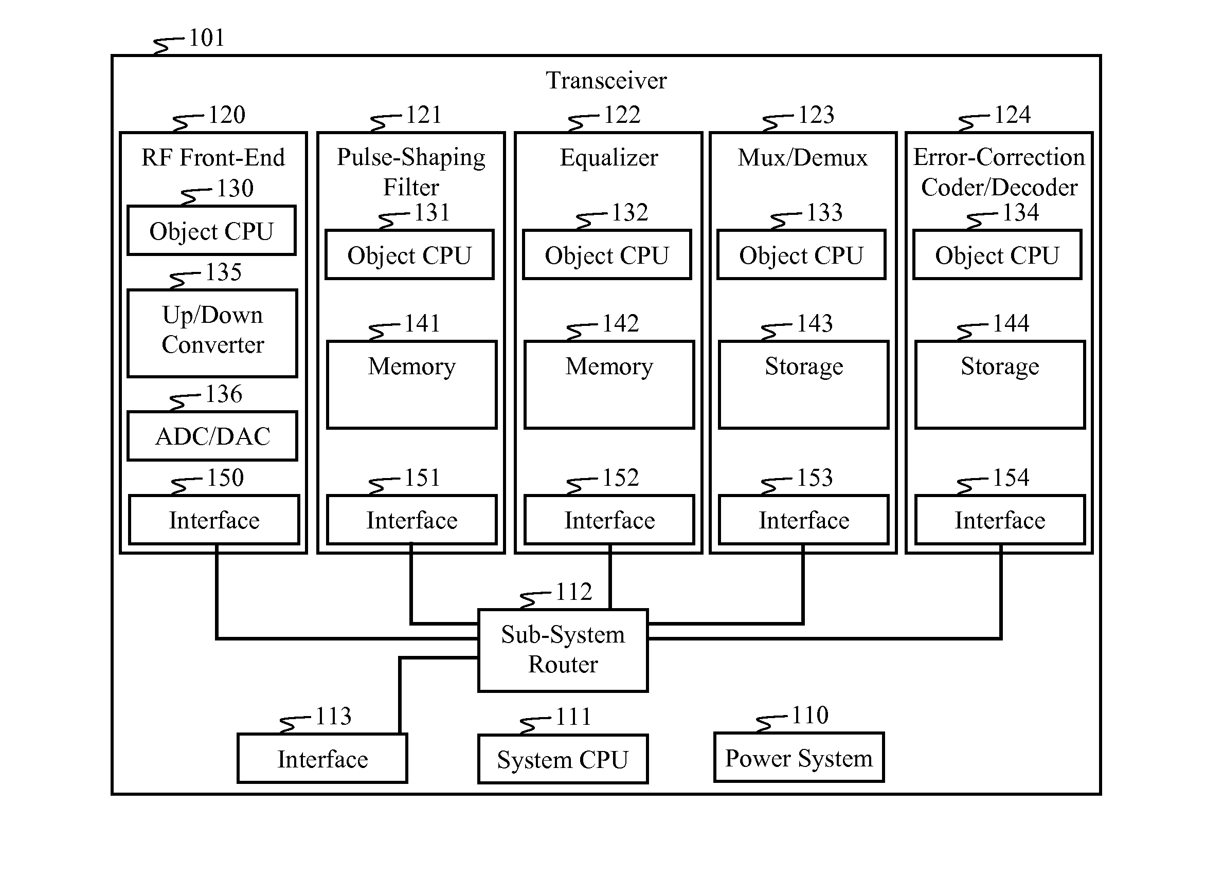
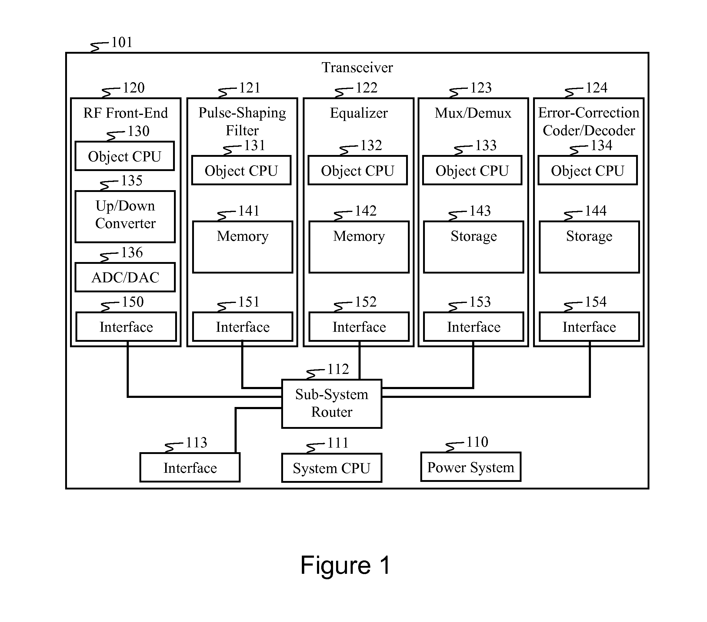
[0034]FIG. 1 is a block diagram of a wireless transceiver 101 in accordance with an aspect of the invention. The transceiver 101 comprises a plurality of rapid-prototyping transceiver components, or objects 120-124. Each object 120-124 comprises a combination of hardware and software configured for “plug-and-play” assembly. The principle of plug-and-play, as used herein, refers to methods and aspects of the invention that facilitate the discovery of a hardware component in a system without the need for physical device configuration or user intervention in resolving resource conflicts.

[0035]Transceiver component...


PUM


Abstract

An electronic object is configured for rapid prototyping of a wireless communication transceiver. The electronic object comprises hardware and software components. An identification module is configured for automatically conveying the electronic object's identity to at least one other electronic object in the transceiver. A signal processor performs object-specific signal processing, which is one of a plurality of component transceiver functions performed by a transceiver. An interface provides access to the electronic object's resources by other electronic objects via physical and logical entry points.

Description

BACKGROUND OF THE INVENTION[0001]I. Field of the Invention[0002]The present invention relates to rapid prototyping of electronic systems, and in particular, to systems and methods for assembling and configuring wireless transceiver components.[0003]II. Description of the Related Art[0004]The performance of a wireless communication network is inseparably linked to the physical layer algorithms on which it is built, the hardware used to implement the wireless links, and the wireless environment in which it operates. One major difficulty with operating a wireless network is the need to replace or redesign hardware when operating requirements change. This well-recognized need in the art has driven the development of software-defined radios in which many of the components that were typically implemented in special-purpose hardware are instead implemented in software by a general-purpose processor. The rationale behind such a design is to enable a radio to transmit and receive a variety o...

Claims


Application Information

Patent Timeline
Patent Type & Authority Applications(United States)
IPC IPC(8): H04B1/38
CPCH04B1/0003H04B1/38
Inventor SEN, ROBISTARNES, IAN CHARLES
Owner GENGHISCOMM HLDG
Learn More