Teleconverter lens system and photographing apparatus including the same
a technology of teleconverter lens and photographing apparatus, which is applied in the field of teleconverter lens system and photographing apparatus including the same, can solve the problems of general lens system limitations in magnification, teleconverter lens typically has a complicated structure, and the effect of high zooming ra
- Summary
- Abstract
- Description
- Claims
- Application Information
AI Technical Summary
Benefits of technology
Problems solved by technology
Method used
Image

Examples
first embodiment
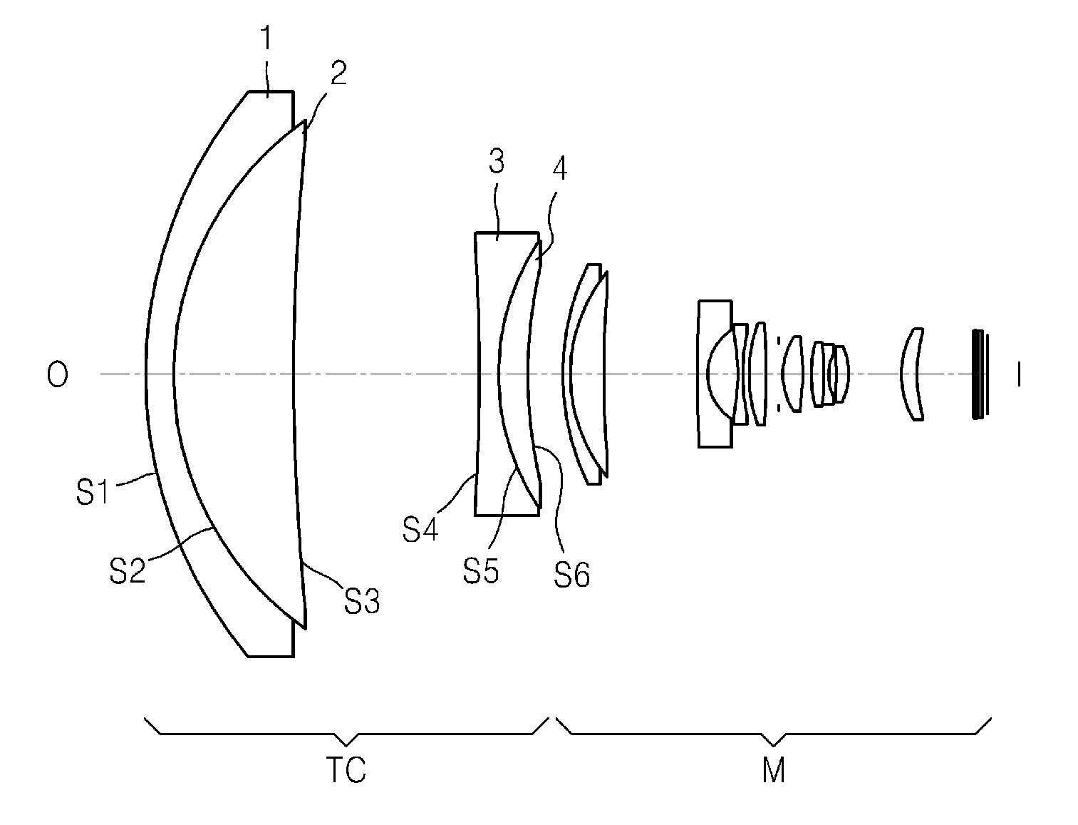
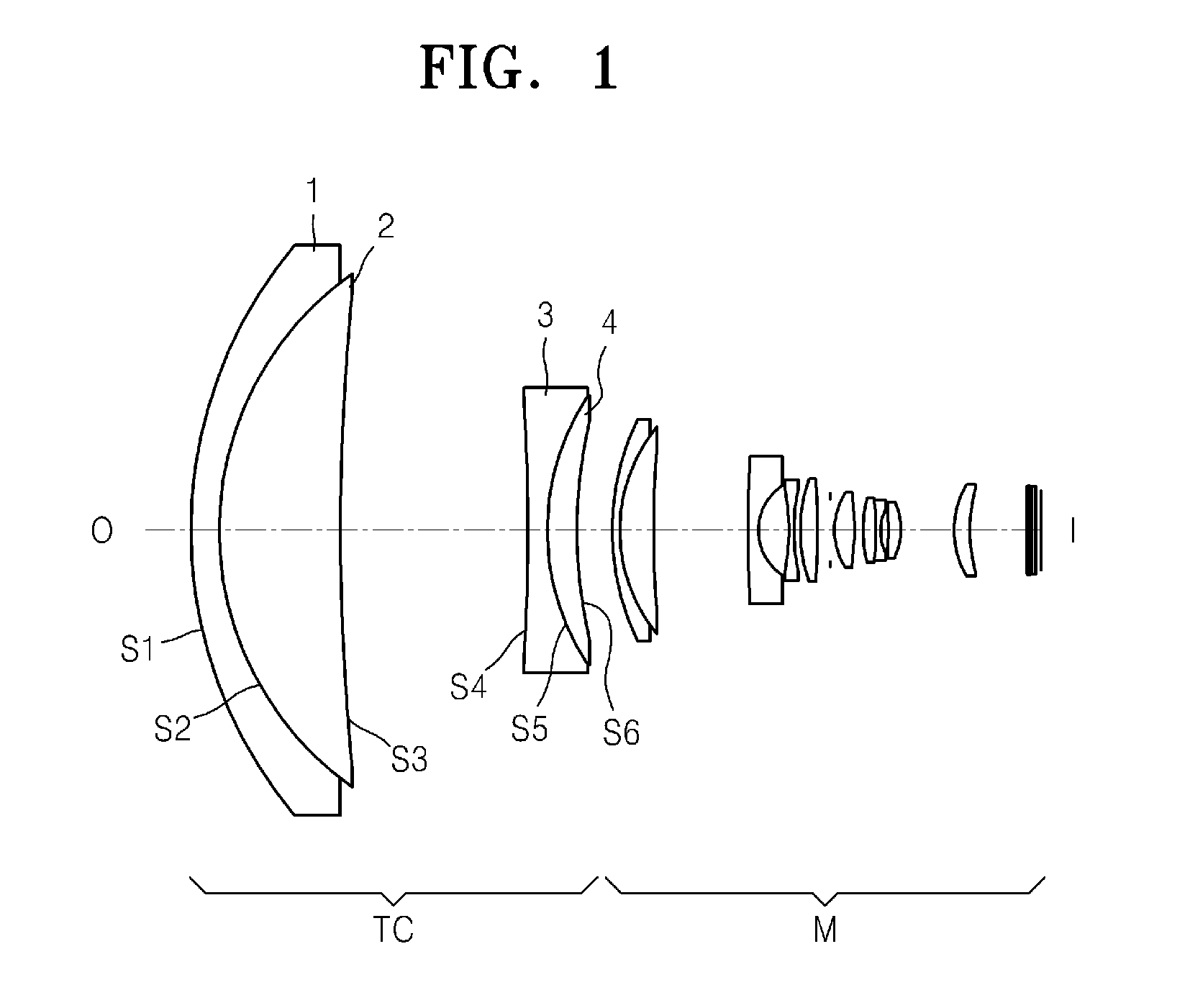
[0037]FIG. 1 illustrates a configuration in which the teleconverter lens system TC according to a first embodiment is combined with the main lens system M. The main lens system M is an example, and should not be construed as limiting.
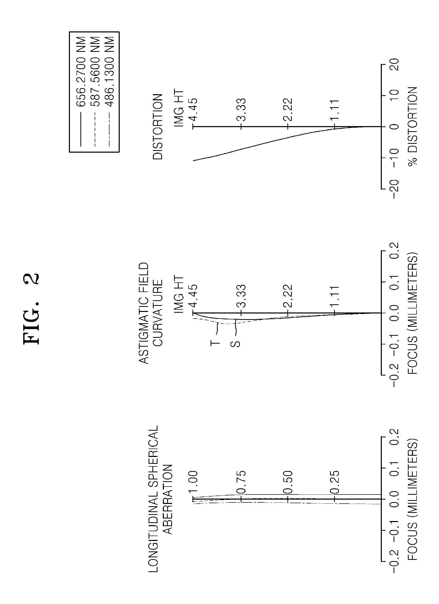
[0038]In the current embodiment, a value of Expression 1 is 2.962, a value of Expression 2 is 1.420, a value of Expression 3 is 28.5, and a value of Expression 4 is 1.668.
[0039]EFL: 25.49 mm, FNO: 3.52, Viewing angle: 20.02°
[0040]
Abbe'sRadius ofRefractivenumberLens surfacecurvatureThicknessindex (nd)(vd)TeleconverterS153.9103.501.80525.4lens systemS238.20014.501.71353.9S3300.00022.7S4−300.0002.31.74349.2.S528.9303.61.62036.3S658.4164.30Main lensS730.5530.901.92320.8systemS819.8794.121.88340.8S9149.57611.35S10*199.9821.251.80540.9S11*6.1703.8S12−27.3910.601.88340.8S1327.3910.78S1418.9592.061.92320.8S15−79.1261.56Stopinfinity0.50S17*8.3062.401.74049.0S18*−23.5190.99S1915.0811.61.48770.4S20−28.7680.501.84723.7S216.9980.942S22−28.108 1.551.49781.6S23−7.4558...
second embodiment
[0044]FIG. 3 is a cross-sectional view of a lens system in which a teleconverter lens system TC is combined with a main lens system M, according to a second embodiment.
[0045]In the current embodiment, a value of Expression 1 is 4.000, a value of Expression 2 is 1.000, a value of Expression 3 is 13.3, and a value of Expression 4 is 1.489.
[0046]EFL: 22.76 mm, FNO: 3.54, Viewing angle: 22.44°
[0047]
Abbe'sRadius ofRefractivenumberLens surfacecurvatureThicknessindex (nd)(vd)TeleconverterS139.8152.001.71227.5lens systemS228.70911.161.88340.8S3219.7636.4S4−1348.2080.51.82835.9S520.5284.21.58061.4S634.2134.20Main lensS730.5530.901.92320.8systemS819.8794.121.88340.8S9149.57611.35S10*199.9821.251.80540.9S11*6.1703.8S12−27.3910.601.88340.8S1327.3910.78S1418.9592.061.92320.8S15−79.1261.56Stopinfinity0.50S17*8.3062.401.74049.0S18*−23.5190.99S1915.0811.61.48770.4S20−28.7680.501.84723.7S216.9980.942S22−28.1081.551.49781.6S23−7.4558.1S24*11.0791.91.80540.9S25*20.7705.2S26infinity0.31.51764.1S27infin...
third embodiment
[0051]FIG. 5 is a cross-sectional view of a lens system in which a teleconverter lens system is combined with a main lens system, according to a third embodiment.
[0052]In the current embodiment, a value of Expression 1 is 2.084, a value of Expression 2 is 1.400, a value of Expression 3 is 23.9, and a value of Expression 4 is 1.701.
[0053]EFL: 26.00 mm, FNO: 3.54, Viewing angle: 19.64°
[0054]
Abbe'sRadius ofRefractivenumberLens surfacecurvatureThicknessindex (nd)(vd)Teleconverter S152.8952.001.92320.8lens systemS238.71714.501.77744.7S3257.09321.4S4−810.4421.01.82329.6S517.3316.91.79823.9S649.3014.70Main lensS730.5530.901.92320.8systemS819.8794.121.88340.8S9149.57611.35S10*199.9821.251.80540.9S11*6.1703.8S12−27.3910.601.88340.8S1327.3910.78S1418.9592.061.92320.8S15−79.1261.56Stopinfinity0.50S17*8.3062.401.74049.0S18*−23.5190.99S1915.0811.61.48770.4S20−28.768 0.501.84723.7S216.9980.942S22−28.108 1.551.49781.6S23−7.4558.1S24*11.0791.91.80540.9S25*20.7705.2S26infinity0.31.51764.1S27infinity...
PUM
 Abstract
Description
Claims
Application Information
 - Generate Ideas
- Intellectual Property
- Life Sciences
- Materials
- Tech Scout
- Unparalleled Data Quality
- Higher Quality Content
- 60% Fewer Hallucinations
Browse by: Latest US Patents, China's latest patents, Technical Efficacy Thesaurus, Application Domain, Technology Topic, Popular Technical Reports.
© 2025 PatSnap. All rights reserved.Legal|Privacy policy|Modern Slavery Act Transparency Statement|Sitemap|About US| Contact US: help@patsnap.com