Electronic equipment, accessory and camera system
a technology of electronic equipment and camera system, applied in the direction of television system, safety/protection circuit, instruments, etc., can solve the problem that the battery capacity cannot be effectively used up, and achieve the effect of effectively or stably using the battery and effectively using up the battery capacity
- Summary
- Abstract
- Description
- Claims
- Application Information
AI Technical Summary
Benefits of technology
Problems solved by technology
Method used
Image
Examples
first embodiment
[0027]An aspect for carrying out the present invention when applying electronic equipment according to the present invention to a digital camera will be described.
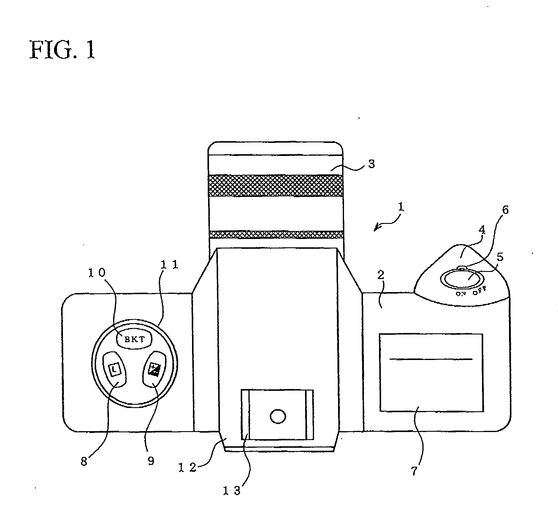
[0028]FIG. 1 is a plan view that shows an exterior of a digital camera 1 according to the present embodiment.
[0029]The digital camera 1 includes a camera body (main body) 2, and a photographing lens 3 that is provided in the front surface of the camera body 2 in a freely attachable or detachable manner. On the left side of the camera body 2 when viewed from the front, a grip portion 4 is provided which is grasped by a photographer during photographing. On an upper surface of the grip portion 4, a release button 5 and a power source switch 6 are provided as photographing shutter buttons. On an upper surface of the camera body 2 of the front side of the release button 5, a display portion 7 including an LCD (Liquid Crystal Display) is provided. On an upper surface of the camera body 2 of an opposite side of the grip portion ...
second embodiment
[0049]FIG. 3 is a block diagram that shows an electrical circuit configuration of the digital camera 1 in a second embodiment according to the present invention.
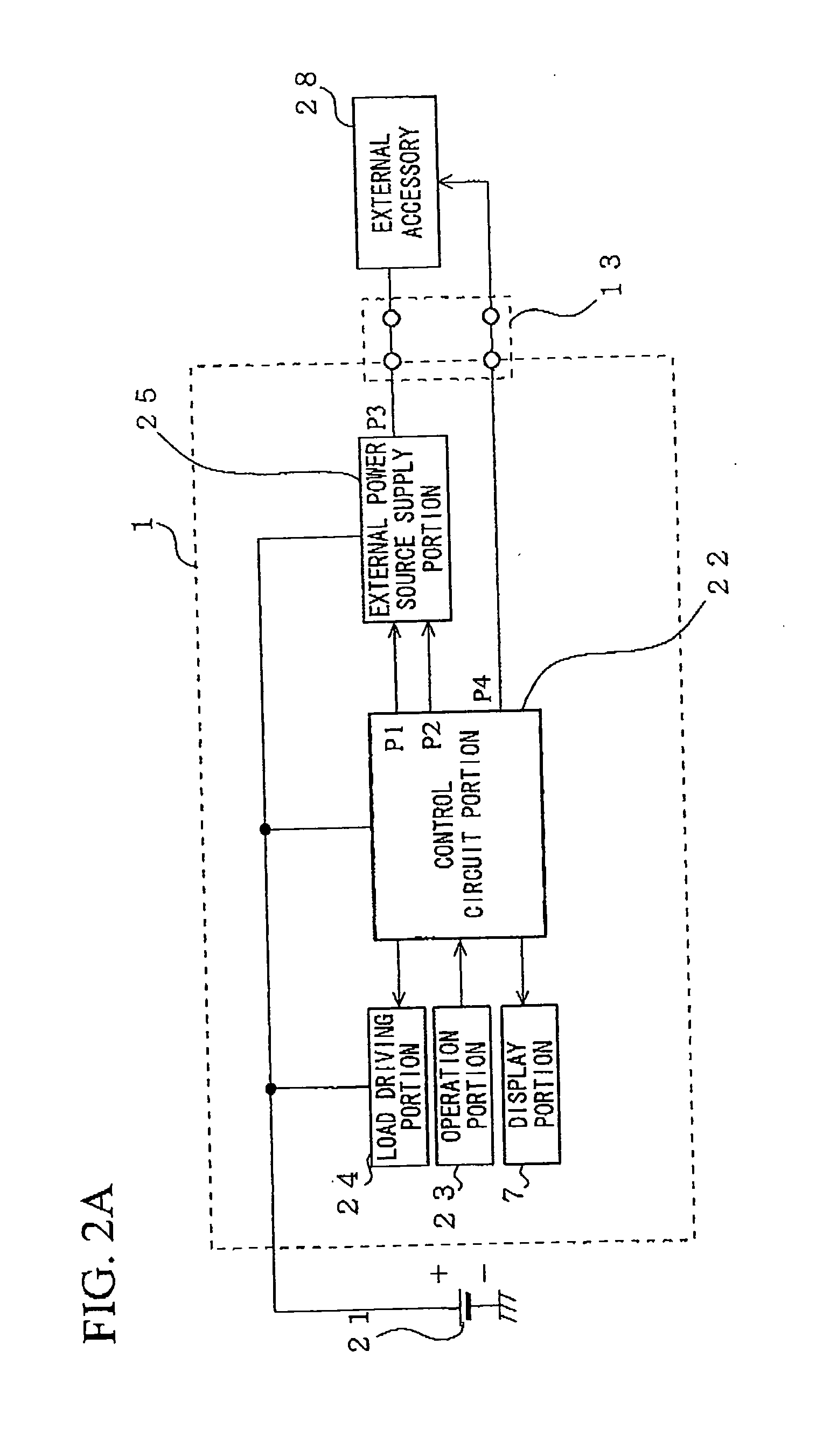
[0050]In FIG. 3, a control circuit portion 22 is configured so as to further include terminals P5, P6 and P7 that can be electrically connected to the external accessory in addition to the configuration shown in the block diagram of FIG. 2A. In an accessory shoe 131, terminals corresponding to the terminals P5, P6 and P7 are provided. In the accessory shoe 131, a terminal of the main body side and a terminal of the external accessory 28 can be electrically and mechanically connected to each other. In the following description, the descriptions on the components common to the block diagram of FIG. 2A will be suitably omitted.
[0051]The digital camera 1 receives a mounting signal from the external accessory 28 via the terminal P5 (a recognition portion) and recognizes the connection with the external accessory 28.
[0052]The digi...
third embodiment
[0067]Next, a third embodiment of the present invention will be described with reference to the drawings.
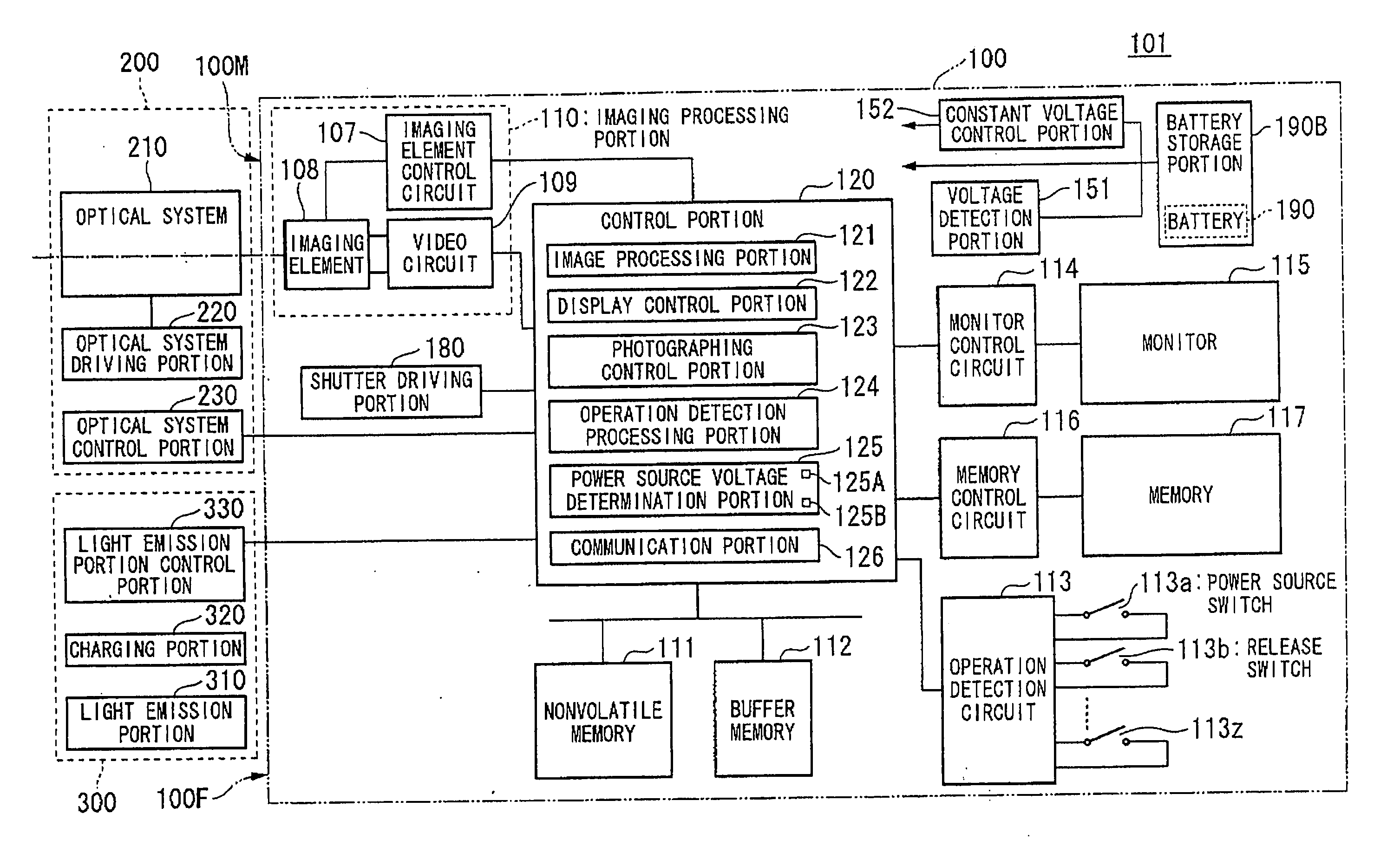
[0068]FIG. 4 is a block diagram that shows a configuration of an imaging device (a camera, a digital camera) according to the present embodiment.
[0069]An imaging device 101 shown in FIG. 4 includes a camera body (main body) 100, and a lens barrel 200 and a light emission device 300 as accessories mounted on the camera body 100.
[0070]In the imaging device 101, the lens barrel 200 includes an optical system 210, an optical system driving portion 220, and an optical system control portion 230.
[0071]The optical system 210 in the lens barrel 200 includes an optical element that adjusts the output of light to the imaging element 108, a barrel portion that protects the optical element or the like. For example, the optical system 210 has a function of adjusting the focus, an aperture function of adjusting the quantity of passing light, a zoom function of changing a photographing angle of...
PUM
 Abstract
Description
Claims
Application Information
 - R&D
- Intellectual Property
- Life Sciences
- Materials
- Tech Scout
- Unparalleled Data Quality
- Higher Quality Content
- 60% Fewer Hallucinations
Browse by: Latest US Patents, China's latest patents, Technical Efficacy Thesaurus, Application Domain, Technology Topic, Popular Technical Reports.
© 2025 PatSnap. All rights reserved.Legal|Privacy policy|Modern Slavery Act Transparency Statement|Sitemap|About US| Contact US: help@patsnap.com


