Label producing apparatus and tape cartridge
a technology of label producing apparatus and tape cartridge, which is applied in the direction of typewriters, printing, other printing apparatus, etc., can solve the problems of inability to accurately detect residual tape amount and inability to always maintain tape thickness constant, so as to achieve the effect of reliably recognizing residual tape amoun
- Summary
- Abstract
- Description
- Claims
- Application Information
AI Technical Summary
Benefits of technology
Problems solved by technology
Method used
Image
Examples
first embodiment
[0078]the present disclosure will now be described with reference to FIGS. 1 to 32.
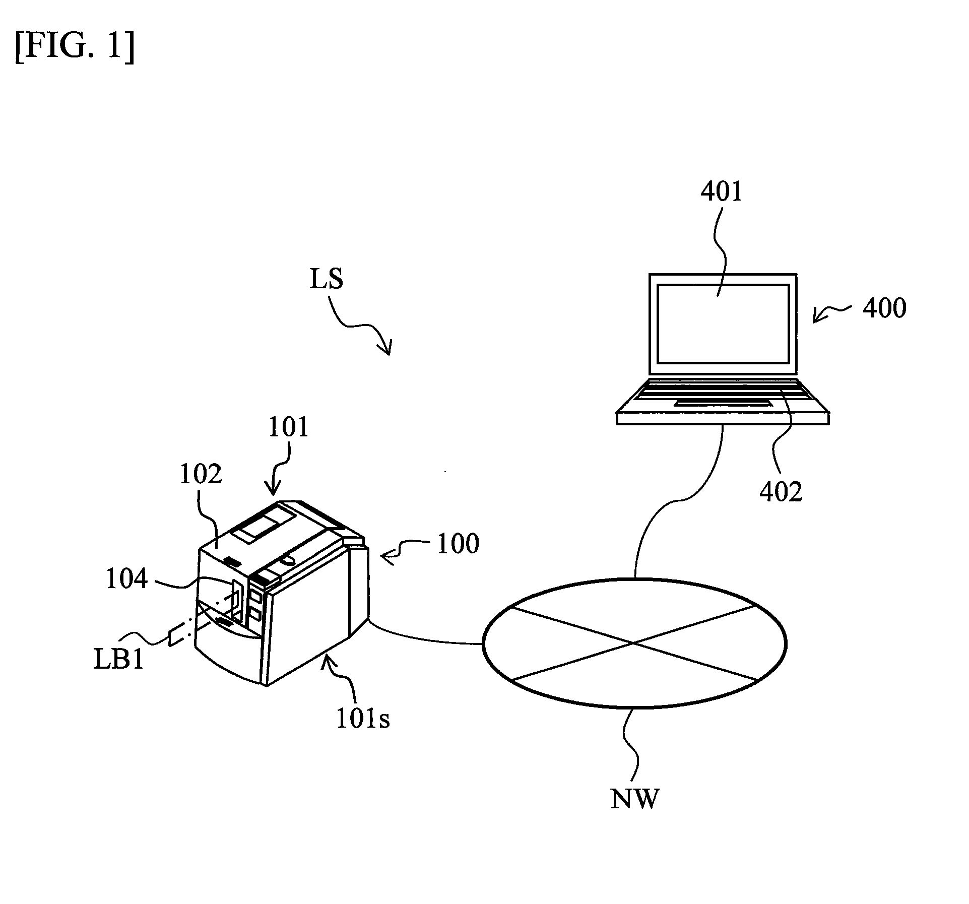
[0079]The configuration of the label producing system of this embodiment will now be described with reference to FIG. 1. In FIG. 1, a label producing system LS comprises a label producing apparatus 100 capable of producing a printed label LB1 (refer to FIG. 9 as well described later) on which desired printing was performed, and an operation terminal 400 for operating the above-described label producing apparatus 100. The label producing apparatus 100 and the operation terminal 400 are connected in an information communicable way via a wired or wireless communication line NW.
[0080]The label producing apparatus 100 has an apparatus main body 101 comprising an apparatus housing 101s of an overall rectangular shape as an outer shell of the label producing apparatus 100. On the upper surface of the apparatus main body 101 is provided an opening / closing lid 102 provided in a manner that enables opening and ...
second embodiment
[0287]In the above-described second embodiment, the detected body 74 that rotates at an angular velocity (the same angular velocity in the above-described example) in coordination with the tape rolls 17, 17′, and 17″ is provided, and the first optical sensor 51 optically detects the detection mark 75 of the detected body 74. Further, the CPU 44 calculates the feeding distance L of the label producing tapes 16, 16′, and 16″. Then, the control circuit 40 calculates the residual tape amount M of the tape rolls 17, 17′, and 17″ based on the aforementioned predetermined calculation formulas using the above-described history information of the pulse cycle E consecutively detected by the plurality of detection mark 75 based on the spool outside diameter d set in advance, the feeding distance L calculated by the CPU 44, and the detection result of the first optical sensor 51, and outputs the residual tape amount information corresponding to the residual tape amount M thus calculated to the ...
third embodiment
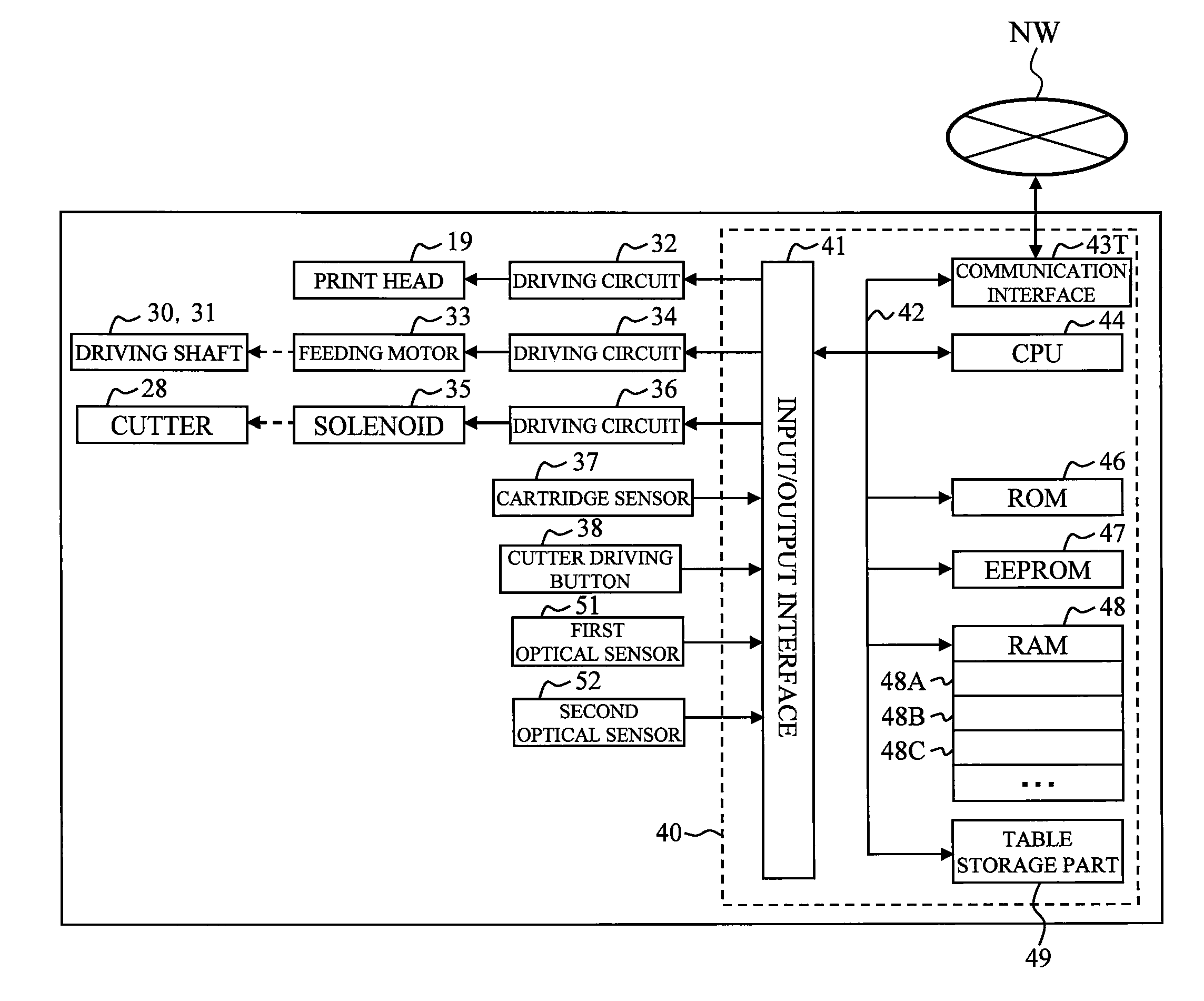
[0324]The detailed procedure of step S100 of the above-described FIG. 11 executed by the control circuit 40 in this third embodiment will now be described with reference to FIG. 38. The description that follows uses as an example the case in FIG. 38 where the printed label LB1 is produced using the cartridge 10 of a laminated type.
[0325]First, in step S3110, the control circuit 40 outputs a control signal (motor pulse signal) to the feeding motor driving circuit 34. As a result, the feeding motor 33 drives the feeding roller driving shaft 30 and the ribbon take-up roller driving shaft 31, thereby starting the feed-out of the base tape 16 from the base tape roll 17 and the feed-out of the cover film 11 from the cover film roll 12. As a result, the feeding of the base tape 16, the cover film 11, and the label tape 23 with print (hereinafter collectively simply referred to as the “base tape 16, etc.”) is started. Further, in this step S3110, calculation of the feeding distance based on...
PUM
 Abstract
Description
Claims
Application Information
 - R&D
- Intellectual Property
- Life Sciences
- Materials
- Tech Scout
- Unparalleled Data Quality
- Higher Quality Content
- 60% Fewer Hallucinations
Browse by: Latest US Patents, China's latest patents, Technical Efficacy Thesaurus, Application Domain, Technology Topic, Popular Technical Reports.
© 2025 PatSnap. All rights reserved.Legal|Privacy policy|Modern Slavery Act Transparency Statement|Sitemap|About US| Contact US: help@patsnap.com


