
Display input device

Active Publication Date: 2011-11-24
MITSUBISHI ELECTRIC CORP
View PDF2 Cites 92 Cited by
  • Summary
  • Abstract
  • Description
  • Claims
  • Application Information

AI Technical Summary

Benefits of technology

[0009]By the way, in the case in which the touch panel is positioned in front of the user's eyes and is mounted in a horizontal position, when the user brings his or her finger close to the enlarged keys (icons) in the display area having a fixed range, the user can easily position his or her finger at the virtual position of an icon. In this case, the touch panel is easy to use.
[0013]The present invention is made in order to solve the above-mentioned problem, and it is therefore an object of the present invention to provide a display input device which provides an improvement in its usability independently upon the operational environment of a touch panel.
[0015]The display input device in accordance with the present invention can provide an improvement in its usability independently upon the operational environment of the touch panel.

Problems solved by technology

However, in the case in which the touch panel is mounted while being inclined on account of its design, the direction extending directly upward from the touch panel (i.e., the direction perpendicular to the surface of the touch panel) does not match the direction extending directly upward from a target icon, which is viewed from the user (i.e., the direction of the line connecting the position of the user's eye and the icon).
Therefore, there occurs a problem that when the user is going to touch “ (se)”, for example, his or her fingertip is actually at the position of “(ku)”, as shown in FIG. 9, and the usability of the touch panel gets worse.
Furthermore, the same problem occurs in the case in which a touch panel is operated from left and right sides with respect to the front of the touch panel, e.g., when a touch panel of a car navigation device is installed in the center of a center console and is operated by the driver on the driver's seat or a passenger on the front seat next to the driver's seat.

Method used


Image

  • Display input device
  • Display input device
  • Display input device

Examples


embodiment 1

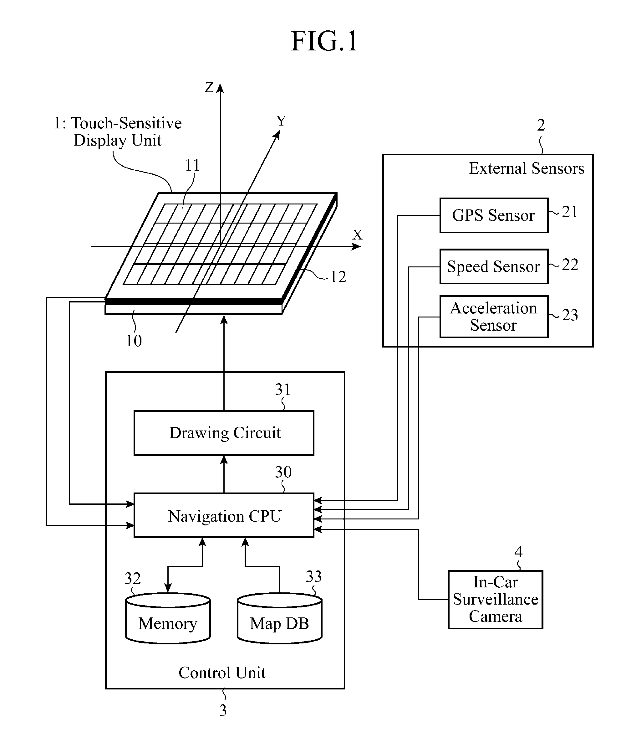
[0026]FIG. 1 is a block diagram showing the structure of a display input device in accordance with Embodiment 1 of the present invention. As shown in FIG. 1, the display input device in accordance with Embodiment 1 of the present invention is comprised of a touch-sensitive display unit (abbreviated as a touch panel from here on) 1, external sensors 2, a control unit 3, and an in-car surveillance camera 4.

[0027]The touch panel 1 carries out a display of information and an input of information. For example, the touch panel 1 is constructed in such a way that a touch sensor 11 for inputting information is laminated on an LCD panel 10 for displaying information. Furthermore, the touch panel 1 and a plurality of proximity sensors 12 each of which carries out non-contact detection in two dimensions of a movement of an object to be detected, such as a finger or a pen, which is positioned opposite to the touch panel 1 are mounted on a peripheral portion outside the touch sensor 11 on a per-...

embodiment 2

[0073]In above-mentioned Embodiment 1, although the example in which only whether or not a user's finger has approached to the touch panel is detected and the detected distance from the touch panel to the position of the finger in a direction of the Z axis is assumed to be a constant value Zref is explained, it can be considered that if the distance between the approaching finger and the touch panel in the Z axial direction can be detected, the strength of the correction is changed according to the distance in the Z axial direction. In this case, it is desirable that the correction is controlled in such a way that it is weakened as the distance between the approaching finger and the touch panel in the Z axial direction increases, whereas the correction is strengthened as the distance between the approaching finger and the touch panel in the Z axial direction decreases.

[0074]More specifically, because the user understands that the accuracy of the detected coordinate position gets wor...

embodiment 3

[0085]The display input device in accordance with any one of above-mentioned Embodiments 1 and 2 of the present invention makes a coordinate position correction by assuming the position of an operator's eye to some extent. In contrast, in Embodiment 3 which will be explained hereafter, an example in which a coordinate position correction is made by assuming a case in which two or more operators exist in a vehicle and the positions of their eyes differ from one another, e.g., a case in which the driver operates a touch panel of a car navigation installed in the center of a center console from the driver's seat and a passenger operates the touch panel from the front seat next to the driver's seat will be explained.

[0086]A display input device in accordance with this embodiment can change the strength of the correction by detecting whether either the driver on the driver's seat or a passenger on the front seat operates the touch panel 1 by performing image processing, as will be explai...


PUM


Abstract

A display input device includes a control unit for correcting horizontal coordinates of an object to be detected on an xy coordinate plane extending on a touch panel 1, which are acquired by a proximity sensor 12, according to an angle of elevation φ, an angle of deviation θ and a vertical distance z between the object to be detected and a surface of the touch panel, φ being the angle of a straight line OC with respect to the surface of the touch panel, the straight line OC extending between a predetermined point O positioned on the touch panel and a predetermined point C positioned outside the touch panel, and θ being the angle between a straight line which is an orthogonal projection of the line OC onto the xy coordinate plane, and an x axis on the xy coordinate plane.

Description

FIELD OF THE INVENTION[0001]The present invention relates to a display input device particularly suitable for use in vehicle-mounted information equipment such as a navigation system.BACKGROUND OF THE INVENTION[0002]A touch panel is an electronic part which is a combination of a display unit like a liquid crystal panel, and a coordinate position input unit like a touchpad, and is a display input device that enables a user to simply touch an image area, such as an icon, displayed on the liquid crystal panel to cause the display input device to detect information about the position of a part of the image area which has been touched by the user, thereby enabling the user to operate target equipment. Therefore, in many cases, a touch panel is incorporated into equipment, such a vehicle-mounted navigation system, which has to mainly meet the need for the user to handle the equipment by following a self-explanatory procedure.[0003]Many proposals for improving the ease of use and usability...

Claims


Application Information

Patent Timeline
IPC IPC(8): G06F3/041G06F3/0481G06F3/0488
CPCG06F3/0416G06F3/0418G06F3/0488G06F3/013G06F2203/04101G06F2203/04108G06F2203/04805G06F3/04886
Inventor SHIMOTANI, MITSUOMATSUBARA, TSUTOMUSADAHIRO, TAKASHIOHTA, MASAKOOKANO, YUICHISEMPUKU, TSUYOSHI
Owner MITSUBISHI ELECTRIC CORP
Learn More