
Device for Drying Bulk Material in at least one Storage Container

a technology for drying devices and bulk materials, applied in the direction of granular material drying, furnaces, separation processes, etc., can solve the problems of requiring significant space and expensive equipment parts for refrigerating devices, and achieve the effect of increasing the temperature differen

Inactive Publication Date: 2011-11-24
MOTAN HLDG
View PDF4 Cites 11 Cited by
  • Summary
  • Abstract
  • Description
  • Claims
  • Application Information

AI Technical Summary

Benefits of technology

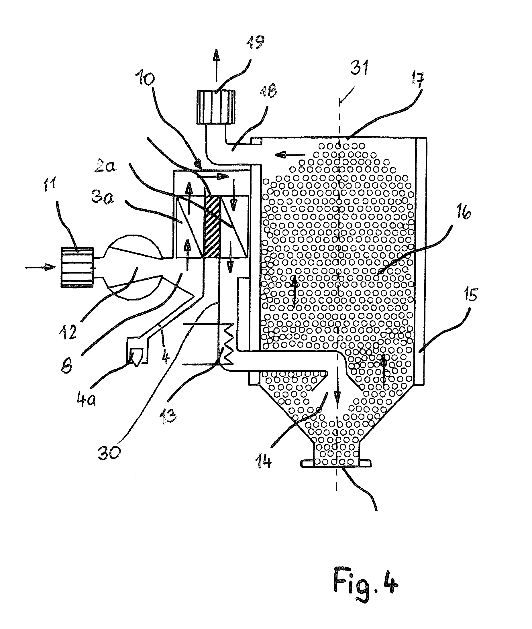
[0006]On the hot side of the Peltier device, the dehumidified drying medium can be heated again so that preheating of the dehumidified drying medium can be achieved. In this way, a significant amount of energy for the drying process is saved.
[0007]The Peltier devices themselves are small plate-shaped Peltier devices with minimal dimensions. The typical dimensions of Peltier devices are between approximately 55 to 100 mm in width, approximately 55 to 100 mm in height, and approximately 4 mm in depth. The Peltier devices thus require little space so that the dehumidifying unit can be designed to be compact. The dehumidifying unit is problem-free in operation but enables still a reliable drying action of the drying medium.
[0011]It is possible to connect to the dehumidifying unit at least one intake conduit for ambient air. The sucked-in ambient air that is generally loaded with moisture is dehumidified within in the dehumidifying unit before it can be supplied as a drying medium to the storage container. Such a configuration is particularly advantageously suited for use in Asian regions in which the ambient air has high humidity. By means of the dehumidifying unit the ambient air can be dehumidified effectively to such an extent that it can be used as a drying medium for drying the bulk material in the storage container.
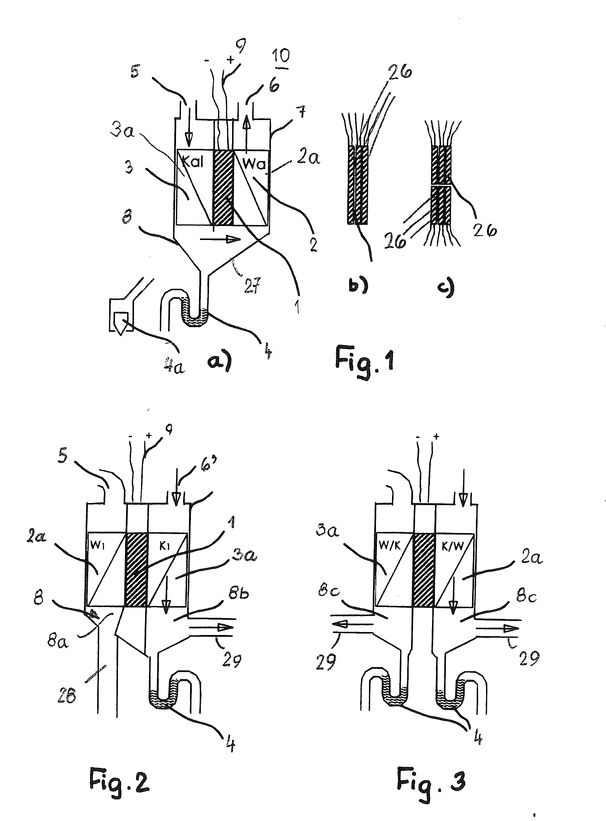
[0013]In order to achieve a high efficiency, it is advantageous when the device has at least two dehumidifying units. In this connection, it is advantageous when the two dehumidifying units are combined such that one dehumidifying unit can be subjected to a deicing process while the other dehumidifying unit, parallel to this deicing process, can be utilized still for dehumidifying the drying medium. Overtime, on the cold side of the Peltier device ice is formed that must be removed in order to be able to perform an optimal dehumidification. As a result of the described advantageous configuration, this deicing process can be performed without having to interrupt the dehumidification process.
[0015]In order to increase the temperature difference, it is advantageous to employ several Peltier devices that can be arranged in a row one after another as well as in a row one after another and in a row adjacent each other within the dehumidifying unit.

Problems solved by technology

Such refrigeration devices are not only expensive facility parts but require also significant space.

Method used


Image

  • Device for Drying Bulk Material in at least one Storage Container
  • Device for Drying Bulk Material in at least one Storage Container
  • Device for Drying Bulk Material in at least one Storage Container

Examples


Embodiment Construction

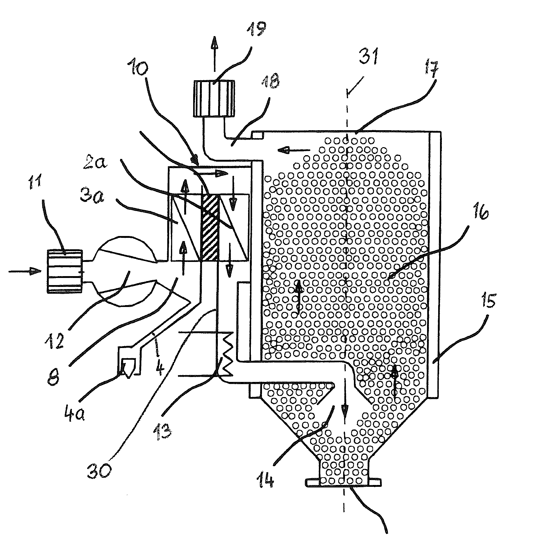
[0036]With the aid of FIGS. 1 to 3 the principle of the device according to the invention for drying bulk material will be explained. For drying the bulk material, dehumidifying units 10 are used that have at least one Peltier device. The dehumidifying unit 10 has a housing 7 that is divided by a partition 1 into two flow chambers 2, 3. The partition 1 is provided with at least one Peltier device 26. As illustrated in FIGS. 1b and 1c, several Peltier devices 26 can be arranged in series one after another (FIG. 1b) but also in series one after another and in series neighboring each other (FIG. 1c). When using several Peltier devices 26 an increase of the temperature difference is possible.

[0037]Peltier devices have the property that, when applying a current, one flat side is heated and the other is cooled down.

[0038]In the embodiment according to FIG. 1a the cold side of the Peltier device 26 is in the flow chamber 3 and the hot side in the flow chamber 2. As a result of the differen...


PUM


Abstract

Before being processed, bulk material is dried in a storage container. A drying medium such as air is passed through the bulk material for drying. The drying medium heats the bulk material and removes moisture at the same time. For dehumidifying the drying medium, a dehumidifying unit with a Peltier device is provided whose cold side and whose hot side are positioned within the flow path of the drying medium. The drying medium loaded with moisture is passed across the cold side and dehumidified. The hot side of the Peltier device is used to preheat the dehumidified drying medium.

Description

BACKGROUND OF THE INVENTION[0001]The invention concerns a device for drying bulk material contained in at least one storage container. At least one supply conduit for a gaseous drying medium, preferably air, opens into the container and at least one outlet conduit is connected to the container into which the drying medium in the form of return air, loaded with moisture after having passed the bulk material, flows. At least one dehumidifying unit is provided with which the drying medium is dehumidified,[0002]Before being processed, bulk material is dried in the storage container for which purpose a drying medium, preferably air, is passed through the bulk material. The drying medium heats up the bulk material and removes at the same time moisture. The drying medium that is loaded with the moisture leaves the storage container through the outlet conduit. This so-called return air is subsequently passed through a drying agent in order to dehumidify the drying medium again and return it...

Claims


Application Information

Patent Timeline
IPC IPC(8): F26B21/08F25B21/02
CPCB01D53/265F26B17/1408F26B2200/08F26B21/086F26B23/04F26B21/04F26B21/083F26B9/06F26B3/04F26B21/02F25B21/02
Inventor KUHNAU, HOLGERHERRO, REINHARD
Owner MOTAN HLDG
Learn More