Gas turbine engine compressor components comprising thermal barriers, thermal barrier systems, and methods of using the same

a technology of thermal barriers and compressor components, which is applied in the direction of machines/engines, liquid fuel engines, mechanical equipment, etc., can solve the problems of increasing temperature and difficulty in getting the material to perform properly

Inactive Publication Date: 2011-11-17
GENERAL ELECTRIC CO
View PDF9 Cites 3 Cited by
  • Summary
  • Abstract
  • Description
  • Claims
  • Application Information

AI Technical Summary

Benefits of technology

[0006]Accordingly, there remains a need for additional measures to protect these materials from the high temperature, high stress environments of the compressor section of a gas turbine engine.

Problems solved by technology

This demand is driven by the requirement to reduce the consumption of fossil fuels, and in turn, operating costs.
However, even with such modifications, there can still be challenges to getting the material to perform properly at increasing temperatures.

Method used


Image

  • Gas turbine engine compressor components comprising thermal barriers, thermal barrier systems, and methods of using the same
  • Gas turbine engine compressor components comprising thermal barriers, thermal barrier systems, and methods of using the same
  • Gas turbine engine compressor components comprising thermal barriers, thermal barrier systems, and methods of using the same

Examples


Embodiment Construction

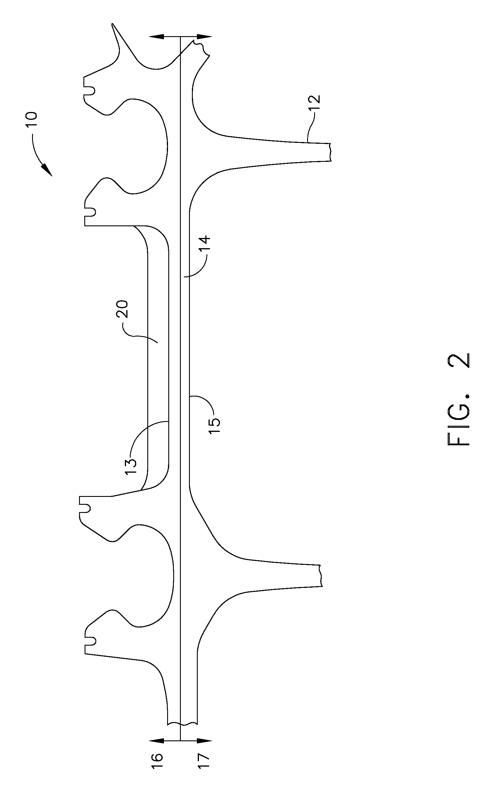
[0014]Embodiments described herein generally relate to gas turbine engine compressor components comprising thermal barriers; thermal barrier systems; and methods of using the same. More particularly, embodiments described herein generally relate to gas turbine engine high pressure compressor shafts and thermal barrier systems for use therewith.

[0015]For purposes of the description herein, the turbine engine compressor component may generally be of any type, however, in one embodiment, the component may be a rotating compressor component, or portion thereof, that experiences a service operating temperature of from about 537° C. (about 1000° F.) to about 788° C. (about 1450° F.), and in one embodiment from about 700° C. (about 1300° F.) to about 788° C. (about 1450° F.). One example of a rotating compressor component that may benefit from the methods and systems described herein can include, but should not be limited to, compressor disks. While the entire disk may be protected, it may...


PUM

PropertyMeasurementUnit
temperatureaaaaaaaaaa
operating temperatureaaaaaaaaaa

Abstract

Gas turbine engine compressor disks having a hot flowpath side; a shaft having a first surface positioned in the hot flowpath side; and a thermal barrier applied to at least the first surface of the shaft where the thermal barrier is operable to maintain the temperature of the shaft below about 700° C. (1300° F.) when the hot flowpath side experiences a service operating temperature of from about 700° C. (1300° F.) to about 788° C. (1450° F.).

Description

CROSS REFERENCE TO RELATED APPLICATIONS[0001]This Application claims priority to U.S. Provisional Application Ser. No. 61 / 345,327, filed May 17, 2010, which is herein incorporated by reference in its entirety.TECHNICAL FIELD[0002]Embodiments described herein generally relate to gas turbine engine compressor components comprising thermal barriers; thermal barrier systems; and methods of using the same. More particularly, embodiments described herein generally relate to gas turbine engine high pressure compressor shafts and thermal barrier systems for use therewith.BACKGROUND OF THE INVENTION[0003]Increasingly stringent demands are being imposed on the efficacy of gas turbine engines employed in the aerospace and power generation industries. This demand is driven by the requirement to reduce the consumption of fossil fuels, and in turn, operating costs. One way to improve turbine efficiency is to increase the operating temperature of the engine. For example, the high pressure compress...

Claims


Application Information

Patent Timeline
Patent Type & Authority Applications(United States)
IPC IPC(8): F04D29/58
CPCY02T50/67F01D5/06F05C2201/0463F05D2300/611F05D2230/90F05D2260/95F05D2300/11F05C2201/0466Y02T50/60
Inventor KONITZER, DOUGLAS GERARDHURON, ERIC SCOTTHAZEL, BRIAN THOMAS
Owner GENERAL ELECTRIC CO
Why Eureka
Try Eureka