Process cartridge and image forming apparatus
a technology of image forming apparatus and process cartridge, which is applied in the direction of electrographic process apparatus, optics, instruments, etc., can solve the problems of development roller not being properly in contact with the electrophotographic photosensitive drum, increasing etc., to increase the amount of load, increase the amount of pressure, and increase the strength
- Summary
- Abstract
- Description
- Claims
- Application Information
AI Technical Summary
Benefits of technology
Problems solved by technology
Method used
Image
Examples
embodiment 1
[0030]First, the first preferred embodiment of the present invention is described.
(General Structure of Image Forming Apparatus)
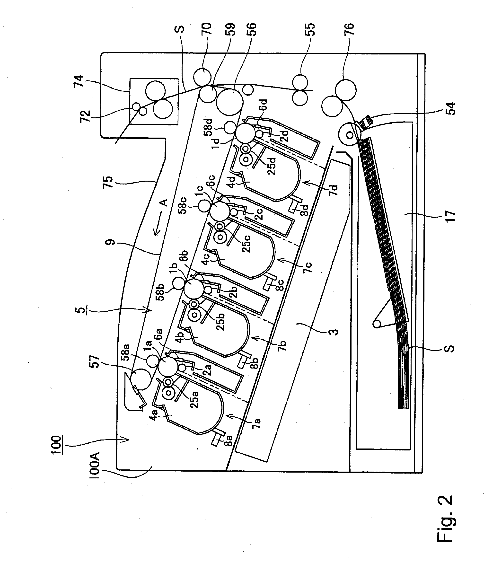
[0031]First, referring to FIG. 2, the overall structure of the electrophotographic image forming apparatus 100 (which hereafter will be referred to simply as image forming apparatus) in this embodiment.
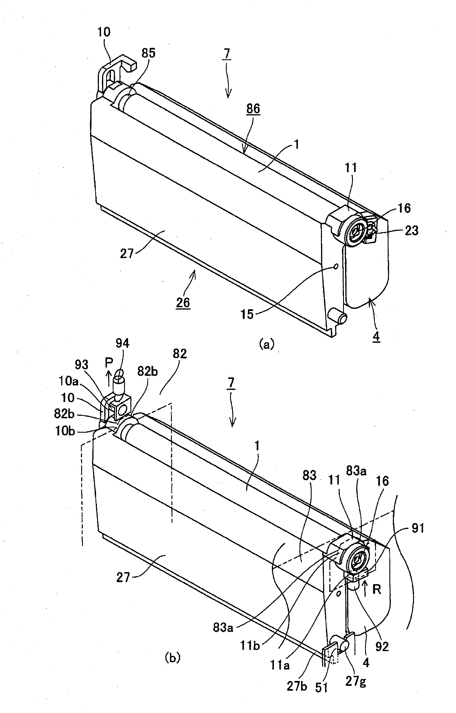
[0032]FIG. 2 is a schematic sectional view of the image forming apparatus 100 in this embodiment, and shows the general structure of the apparatus. The image forming apparatus 100 employs four process cartridges 7 (7a, 7b, 7c, and 7d), which are removably mountable in the main assembly of the apparatus 100 with the use of a process cartridge mounting member (unshown), as shown in FIG. 2. Referring to FIG. 2, the process cartridges 7 (7a, 7b, 7c, and 7d) are positioned in the main assembly 100A of the image forming apparatus 100 (which hereafter will be referred to simply as apparatus main assembly 100A) in parallel at a preset angle relative to the horizontal...
embodiment 2
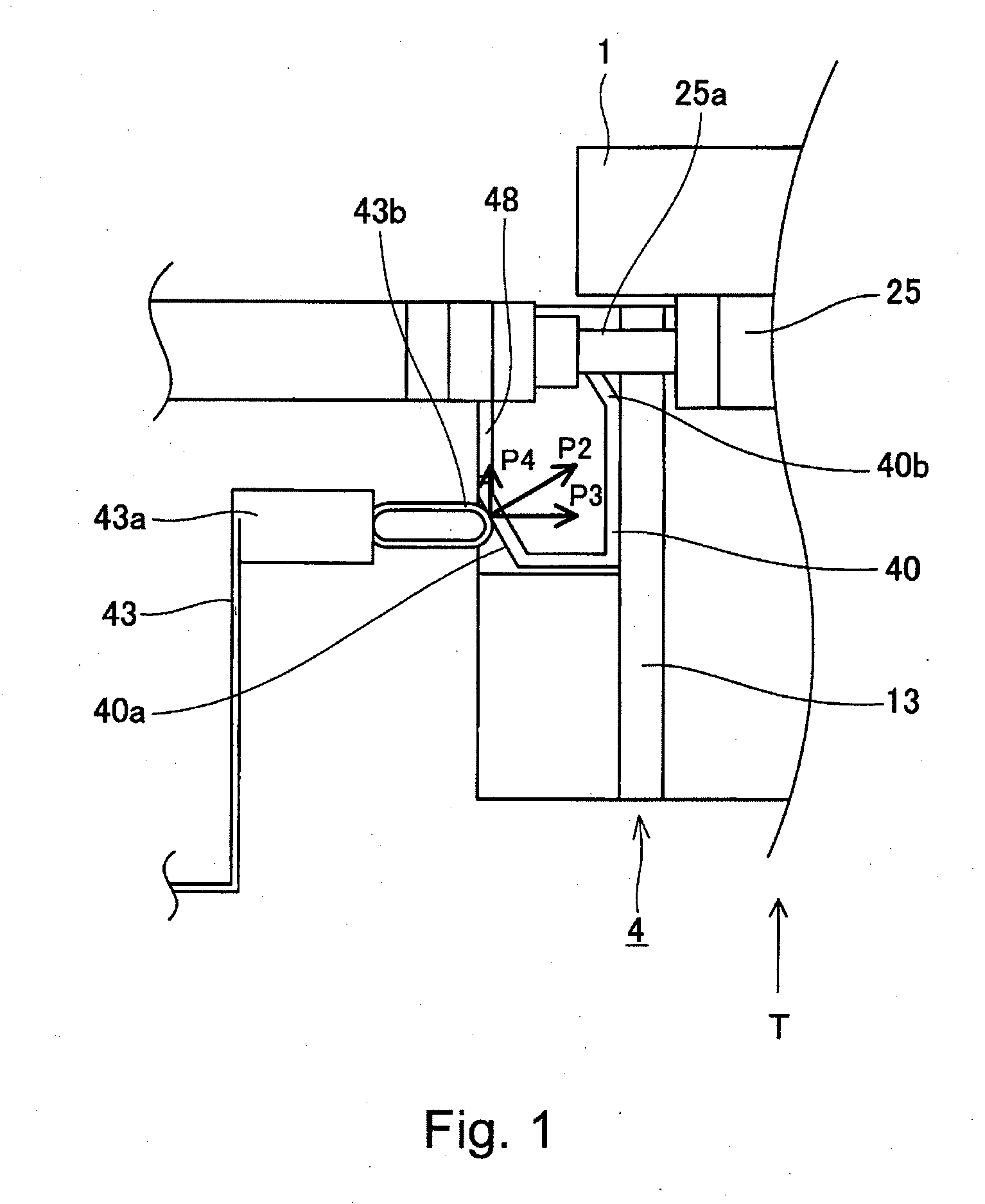
[0082]Next, referring to FIG. 16, the second embodiment of the present invention is described. The components, portions, and the like, of the image forming apparatus and process cartridge in this embodiment, which are similar to the counterparts in the first embodiment are given the same referential codes as those given to the counterparts in the first embodiment, and will not be described here. FIG. 16 is a schematic sectional view of the electrical contacts of the process cartridge 7, electrical contacts of the apparatus main assembly 100A, and their adjacencies in this embodiment when the development unit 4 is in the separation position.
[0083]Referring to FIG. 16, the primary characteristic feature of this embodiment is that when the development unit 4 is in the separation position, that is, the position in which the development roller 25 is kept separated from the photosensitive drum 1, the compression spring 43a of the development bias contact 43 is in contact with the electric...
embodiment 3
[0086]Next, referring to FIG. 17, the third preferred embodiment of the present invention is described. The components, parts, etc. of the image forming apparatus and process cartridge in this embodiment, which are similar to the counterparts in the preceding embodiments are given the same referential codes as those for the counterparts, and are not described. FIG. 17 is a schematic sectional view of the electrical contacts of the process cartridge 7 and the electrical contacts of the apparatus main assembly 100A in this embodiment, when the development unit 4 is in the separation position.
[0087]The primary characteristic feature of this embodiment is that when the development unit 4 is in the separation position, that is, the position in which the development roller 25 is kept separated from the photosensitive drum 1, the compression spring 43a of the development bias contact 43 is not in contact with the process cartridge 7, as shown in FIG. 17.
[0088]More specifically, the side co...
PUM
 Abstract
Description
Claims
Application Information
 - R&D
- Intellectual Property
- Life Sciences
- Materials
- Tech Scout
- Unparalleled Data Quality
- Higher Quality Content
- 60% Fewer Hallucinations
Browse by: Latest US Patents, China's latest patents, Technical Efficacy Thesaurus, Application Domain, Technology Topic, Popular Technical Reports.
© 2025 PatSnap. All rights reserved.Legal|Privacy policy|Modern Slavery Act Transparency Statement|Sitemap|About US| Contact US: help@patsnap.com


