
Dynamoelectric device

a dynamoelectric device and dynamoelectric technology, applied in the direction of cycle equipment, optical signal, magnetic circuit shape/form/construction, etc., can solve the problems of reducing the effectiveness of dynamoelectric devices and increasing the resistance of coils, and achieve the effect of simple energy transpor

Inactive Publication Date: 2011-11-10
ELECTRIC GORILLA
View PDF19 Cites 26 Cited by
  • Summary
  • Abstract
  • Description
  • Claims
  • Application Information

AI Technical Summary

Benefits of technology

[0039]Optionally, the device further comprising a removable energy storage system for the simple transport of energy generated by the device. In an exemplary embodiment of the invention, the generator is a dynamoelectric device and the removable energy storage system includes a power conditioning circuit and a battery. Optionally, the generator is a dynamoelectric device and the removable energy storage system includes a power conditioning circuit and a capacitor.

Problems solved by technology

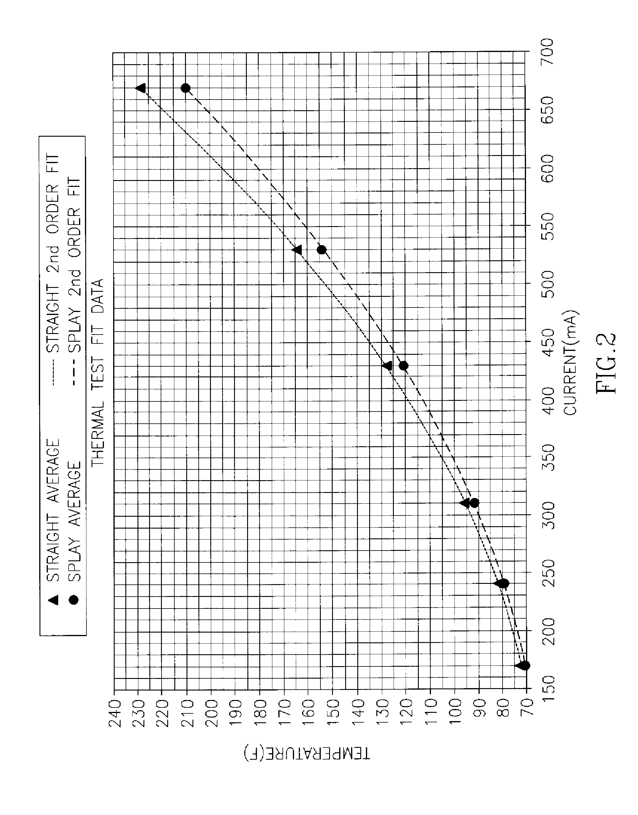
The current flowing in the coil produces heat, which also increases the resistance of the coil and reduces the effectiveness of the dynamoelectric device.

Method used


Image

  • Dynamoelectric device
  • Dynamoelectric device
  • Dynamoelectric device

Examples


Embodiment Construction

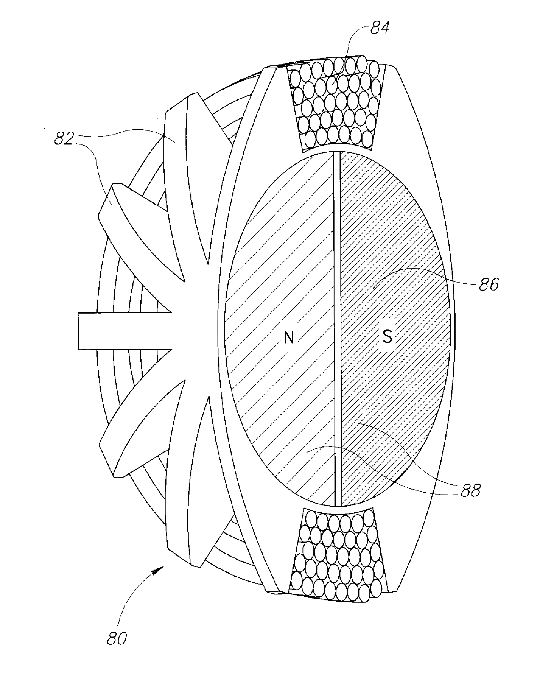
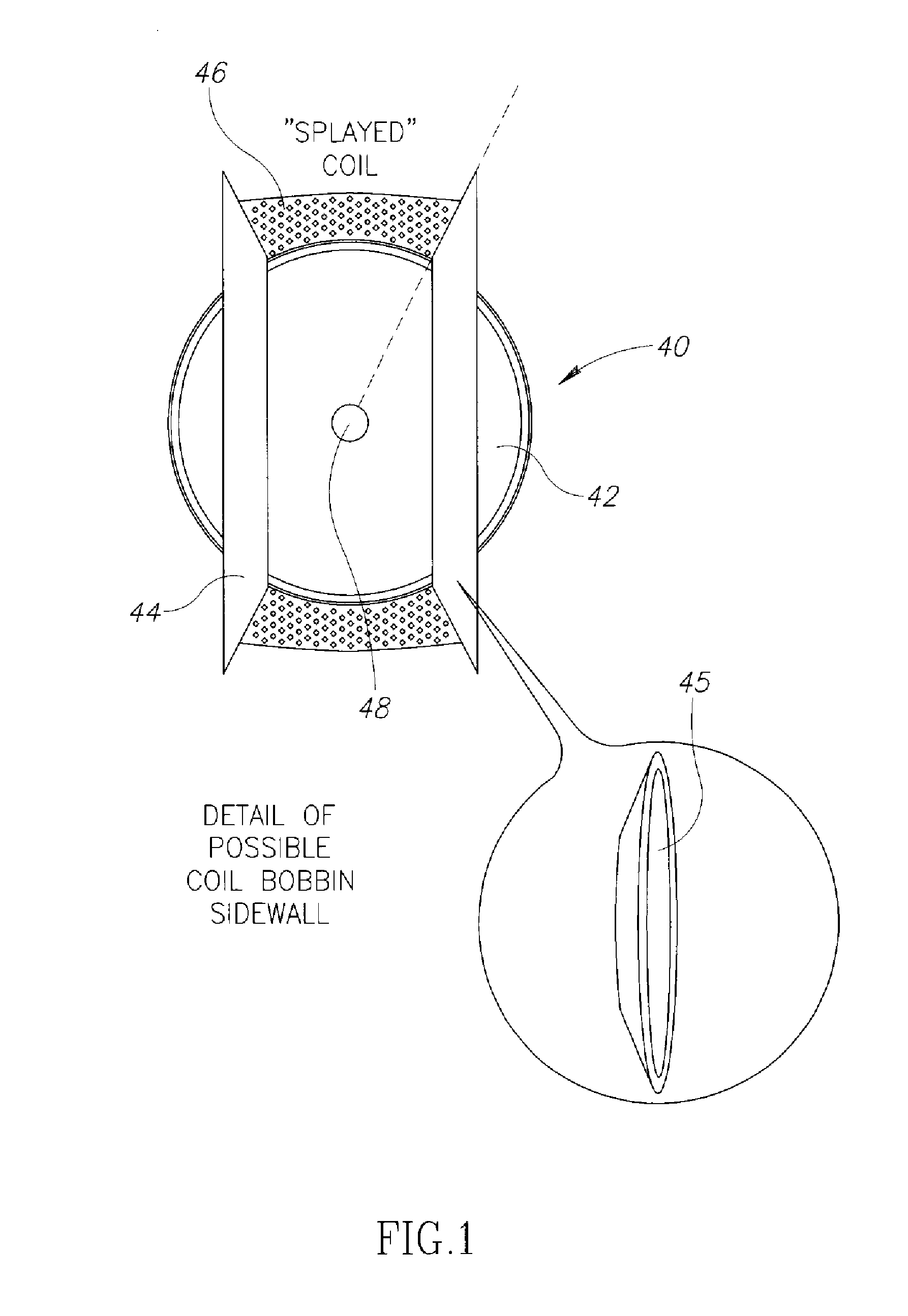
[0082]The disclosure describes various dynamoelectric devices having air-core stators in which the coils have side edges which are splayed or beveled. The splay enables a reduction in the thermal conductive resistance of the shortest thermal dissipation path, that is, the path through the thickness of the winding along a radially outward direction. In several of these designs. a brush-less stator having a bobbin-type, axial-centered coil conductor provides a total capture of magnetic flux emanating from a rotor having an entire surface area of uniform flux density.

[0083]Typically, bobbin-type stator structures have been used in a number of dynamoelectric devices such as alternators, generators, motors, and actuators, for example. The rotors used with such bobbin-type stator structures can include permanent magnet cylinders, discs, truncated spheres, and spherical shapes having selectable numbers of poles, for example. Also, electromagnetic rotors can be used.

[0084]Applications using...


PUM


Abstract

A device, including a rotor, a stator, a coil wound around the stator, wherein the stator has a coil support structure having at least one side edge arranged along a line which is not parallel to a line extending from an axis of the rotor through a center of the coil.

Description

RELATED APPLICATION[0001]This application claims priority from U.S. Provisional Application No. 61 / 258.921 filed Nov. 6, 2009 the disclosure of which is incorporated by reference.FIELD OF THE INVENTION[0002]The present invention relates generally to dynamoelectric devices.BACKGROUND OF THE INVENTION[0003]Dynamoelectric devices include among other things electric generators, alternators, actuators, and motors. An electric generator is a device that converts mechanical energy to electrical energy. In contrast an electrical motor converts electrical energy to mechanical energy. A typical electrical generator includes a stationary structure referred to as the stator, and a rotating part referred to as the rotor. Typically the rotor includes permanent magnets or electro magnets that are designed to rotate relative to a coil that is wound around the stator. The motion of the magnets relative to the coil produces electrical current in the coil. The current producing coil is also called an ...

Claims


Application Information

Patent Timeline
Patent Type & Authority Applications(United States)
IPC IPC(8): H02K3/04
CPCB62J6/06B62J6/20H02K7/1846H02K16/02H02K21/145H02K2203/12H02J7/0068H02J7/32H02K1/12H02K3/28F03G5/06
Inventor LONG, JOHNVADEN, DAVID R.RUTHERFORD, CRAIG
Owner ELECTRIC GORILLA
Learn More