
Cosmetics receptacle

a technology of receptacles and brushes, applied in the field of receptacles, can solve the problems of inconvenient use of brushes, and achieve the effects of stably maintaining the clean state of brushes, convenient use of brushes, and long holding areas

Active Publication Date: 2011-11-10
TAESUNG IND
View PDF7 Cites 9 Cited by
  • Summary
  • Abstract
  • Description
  • Claims
  • Application Information

AI Technical Summary

Benefits of technology

[0017]Accordingly, the present invention has been made to solve the above-mentioned problems occurring in the prior art, and the present invention provides a cosmetics receptacle which can be easily used and allows the clean state and the arrangement state of a brush to be stably maintained.
[0020]According to the present invention, the brush holder is provided in the guide tube part in such a manner that it can move along the length-wise direction of the guide tube part combined with the upper end of the container cap. Also, the brush is combined with the brush holder in such a manner that it can be exposed by passing the lower end of the guide tube part when the brush holder is moved. Thus, the use of the brush can be easy because the holding area is lengthened when the brush is used.
[0021]Furthermore, when kept, the brush is advanced to the inside of the guide tube part. Thus, it is possible to stably maintain the clean state of the brush. Also, when the brush is advanced to the inside of the guide tube part, the brush hairs are put together by the guide tube part. Thus, it is possible to stably maintain the arrangement state of the brush.

Problems solved by technology

However, in the conventional cosmetics receptacle, the container cap 121 (functioning as a brush holder of the present invention) has to be held to move the brush 123, which has caused a problem in that the use of the brush is inconvenient due to the short holding section.

Method used


Image

  • Cosmetics receptacle
  • Cosmetics receptacle
  • Cosmetics receptacle

Examples


Embodiment Construction

[0031]Hereinafter, the present invention will be described in detail with reference to the accompanying drawings.

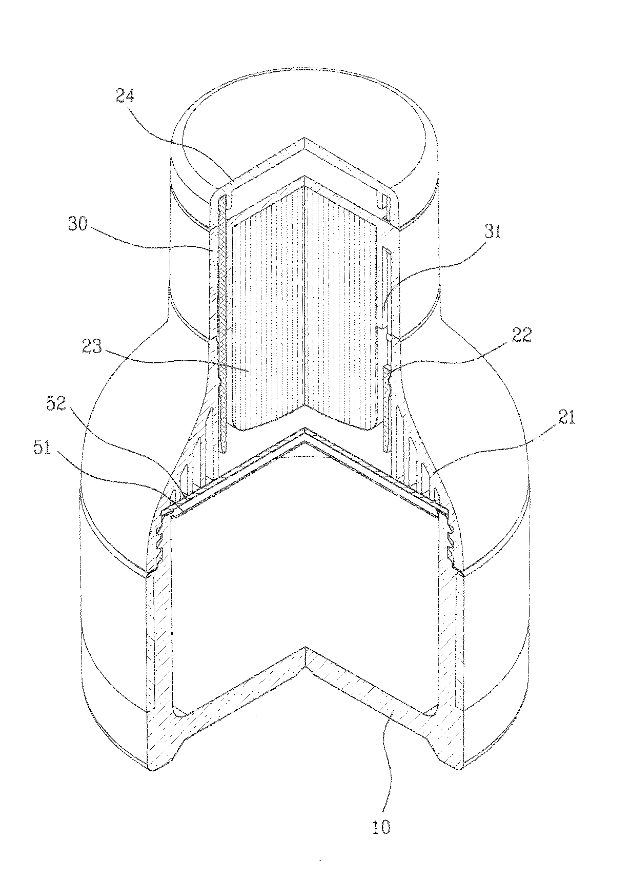
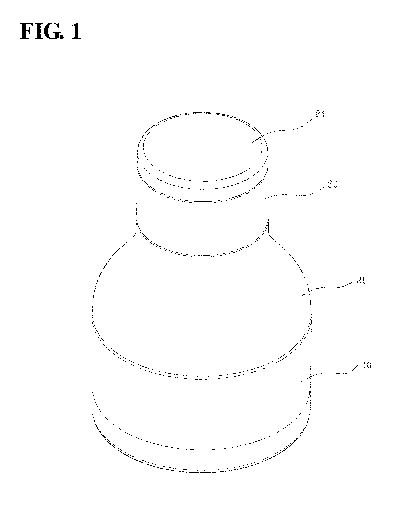
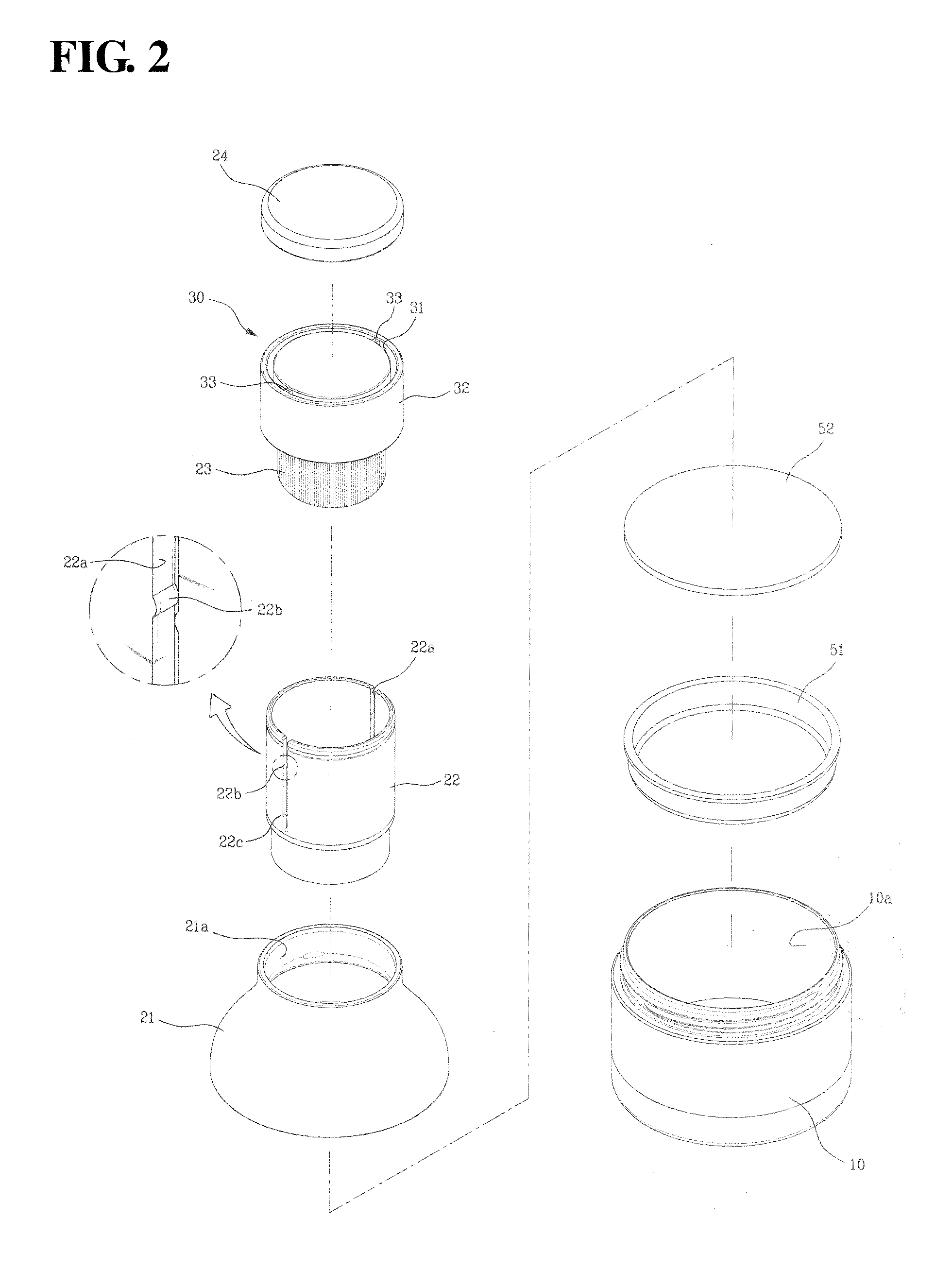
[0032]FIG. 1 is an assembled perspective view illustrating a cosmetics receptacle according to an embodiment of the present invention, FIG. 2 is an exploded perspective view illustrating a cosmetics receptacle according to an embodiment of the present invention, FIG. 3 is a partially cut-away cross-sectional view illustrating a cosmetics receptacle according to an embodiment of the present invention, and FIG. 4 is a detailed view illustrating a brush holder area of a cosmetics receptacle according to an embodiment of the present invention.

[0033]The cosmetics receptacle according to an embodiment of the present invention, as shown in the drawings, includes a container part 10 having a container opening 10a, a container cap 21 combined with the container part 10 in such a manner that it can open / close the container opening 10a, a guide tube part 22 combined with the upper e...


PUM


Abstract

Disclosed is a cosmetics receptacle which has a container part having a container opening, and a container cap combined with the container part in such a manner that the container cap opens and closes the container opening, the cosmetics receptacle including: a guide tube part which includes a pair of guide grooves dotted-formed from an upper end along a length-wise direction, and each of the guide grooves being formed with an upper stopper protrusion; a brush holder having a tube-shaped brush seating tube with a closed upper side, a sliding tube disposed in such a manner that the sliding tube surrounds the brush seating tube, and a pair of guide projections extending from an outer surface of the brush seating tube; a brush mounted in the brush seating tube in such a manner that the brush is exposed by passing the lower end of the guide tube part when the brush holder moves along the length-wise direction of the guide tube part; and a separation preventing cap combined with the upper end of the guide tube part in such a manner that the separation preventing cap is disposed at the upper side of the brush holder. This makes it possible to easily use the brush, and to stably maintain the clean state and the arrangement state of the brush.

Description

BACKGROUND OF THE INVENTION[0001]1. Field of the invention[0002]The present invention relates to a cosmetics receptacle, and more particularly to a cosmetics receptacle having a container part for storing cosmetics in a powder type, a liquid type or a solid type, and a brush for retrieving and applying the cosmetics stored in the container part.[0003]2. Description of the Prior Art[0004]Some cosmetic products such as eye-shadow, cosmetic powder, etc., have to be applied on a facial treatment area by using a brush. For such cosmetic products using a brush, as described above, a cosmetics receptacle which has a container part for storing cosmetics and a brush for retrieving and applying the cosmetics stored in the container part has been invented and used.[0005]FIG. 6 is an assembled perspective view illustrating a conventional cosmetics receptacle, FIG. 7 is an exploded perspective view illustrating a conventional cosmetics receptacle, and, FIG. 8 is a cross-sectional view illustrati...

Claims


Application Information

Patent Timeline
Patent Type & Authority Applications(United States)
IPC IPC(8): A45D33/00
CPCA45D33/006A45D34/045A46B2200/1046A46B11/00A45D40/265A45D33/28B65D43/0225B65D51/32
Inventor BAE, HAE DONG
Owner TAESUNG IND
Learn More