Digital oscilloscope and method for controlling the same

Active Publication Date: 2011-11-03
RIGOL TECH CO LTD
View PDF6 Cites 13 Cited by
  • Summary
  • Abstract
  • Description
  • Claims
  • Application Information

AI Technical Summary

Benefits of technology

[0020]In said digital oscilloscope according to the present invention, said controller may further set the degree of said attenuation according to the length of the time interval of said trigger signal.
[0023]The digital oscilloscope and the method for controlling the digital oscilloscope according to the present invention can adapt to the detected signal automatically and adopt different display method. In particular, the dynamic fluorescence effect is selected automatically for the case where it is necessary to pay attention to the long-term variation of a signal such that the trace intensity information reflects the time characterization of the trace itself and the sequencing between traces. On other hand, the static fluorescence effect is selected automatically for the case where it is necessary to pay attention to the rapid variation of a signal such that the digital oscilloscope has a higher trace capture rate and use the trace intensity information to reflect the frequency of the occurrence of the trace and the variation of the trace itself.

Problems solved by technology

However, since the dynamic fluorescence effect is a display effect in a variable intensity mode, that is, the common real-time display manner, the digital oscilloscope has to occupy a lot of system resources to continuously attenuate the residual trace information, and a new waveform trace may be imposed only after the attenuation process on the residual trace information is completed, therefore for the digital oscilloscope having the dynamic fluorescence effect, more system resources are consumed and waveform capture rate is lower, such that some transient waveform traces can not be captured and observed.
Although the method in which the user sets the display effect of the digital oscilloscope manually is simple, it brings about a problem of continuously adjusting the display manner of the digital oscilloscope to the user of the digital oscilloscope in the case that the detected signal is inconstant.

Method used


Image

  • Digital oscilloscope and method for controlling the same
  • Digital oscilloscope and method for controlling the same
  • Digital oscilloscope and method for controlling the same

Examples


Embodiment Construction

[0028]The digital oscilloscope and the method for controlling the same according to the exemplary embodiments of the present invention will be described below in more detail with reference to the drawing.

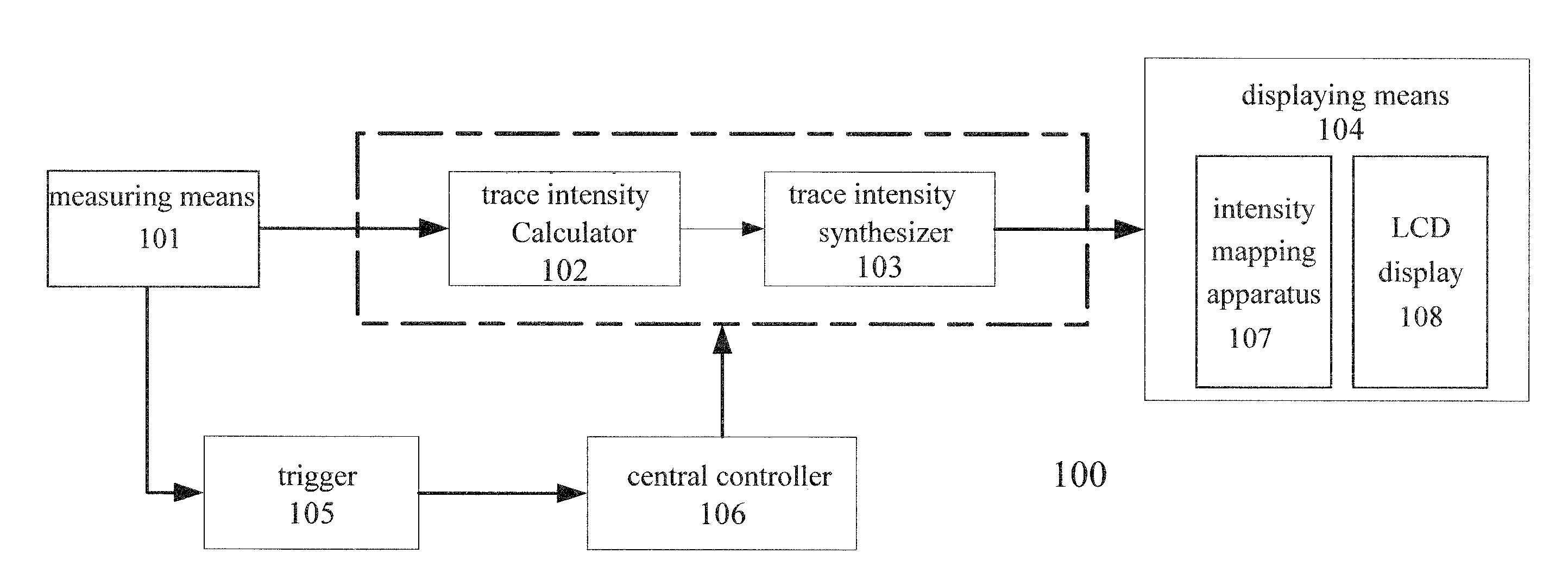
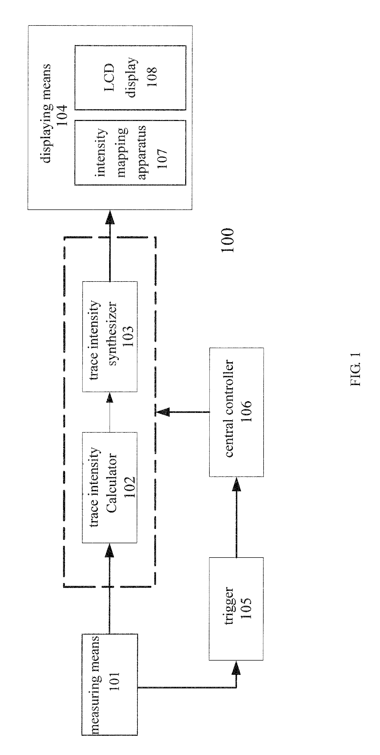
[0029]FIG. 1 is a schematic structure diagram of the digital oscilloscope 100 according to an exemplary embodiment of the present invention.

[0030]With reference to FIG. 1, the digital oscilloscope 100 includes a measuring means 101, a trace intensity calculator 102, a trace intensity synthesizer 103, a displaying means 104, a trigger 105, and a central controller 106.

[0031]The measuring means 101 receives the detected signal, rectifies the detected signal, and digitally samples the detected signal. The measuring means 101 obtains and outputs a digitally sampled signal while outputting the rectified detected signal to the trigger 105.

[0032]The trigger 105 generates a trigger signal according to the rectified detected signal generated by the measuring means 101 or the digitally sample...


PUM


Abstract

Provided are a digital oscilloscope and a method for controlling the same. The digital oscilloscope comprises a trace intensity synthesizer (303) including a first intensity memory (310) and a second intensity memory (320). The controlling procedure (400) performed by the digital oscilloscope includes: a determining step (420) for determining whether the time interval of a trigger signal is larger than a predetermined threshold, a first fluorescence processing step (430) performed when the time interval of a trigger signal is equal to or less than the predetermined threshold, and a second fluorescence processing step (440) performed when the time interval of a trigger signal is larger than the predetermined threshold. The digital oscilloscope according to the present invention can automatically select the dynamic fluorescence effect to pay attention to the long-term variation of a signal when the triggering rate is low, and the static fluorescence effect to pay attention to the rapid variation of a signal when the triggering rate is high. The digital oscilloscope according to the present invention has a compact structure and has a higher waveform capture rate.

Description

FIELD OF THE INVENTION[0001]The present invention relates to a technique of a digital oscilloscope, and in particular a digital oscilloscope and method for controlling the same.DESCRIPTION OF RELATED ART[0002]The display system of a traditional analog oscilloscope adopts a Cathode Ray Tube (CRT). CRT has an excellent fluorescence effect (i.e. the activation effect of the fluorescent powder), which makes the trace of the displayed waveform become dark from bright with the lapse of time, such that the characterizations of the waveform are represented in two aspects: one is the variation of the trace itself, and another is the frequency of reoccurrence of the trace.[0003]At present, the display system of the digital oscilloscope mainly adopts a Liquid Crystal Display (LCD) screen which likes a pixel array arranged in two dimensions, and each pixel position in the pixel array can be determined uniquely by a row address and a column address. Each pixel on the LCD display screen can be im...

Claims


Application Information

Patent Timeline
IPC IPC(8): G06F19/00
CPCG01R13/0227
Inventor WANG, YUEWANG, TIEJUNLI, WEISEN
Owner RIGOL TECH CO LTD
Why Eureka
Try Eureka