
Methods and systems for controlling liquids in multiplex assays

a technology of multiplex assay and liquid control, applied in the field of biological and chemical analysis, can solve the problems of reducing the available space on the microarray, affecting the quality of the sample,

Active Publication Date: 2011-11-03
ILLUMINA INC
View PDF8 Cites 0 Cited by
  • Summary
  • Abstract
  • Description
  • Claims
  • Application Information

AI Technical Summary

Benefits of technology

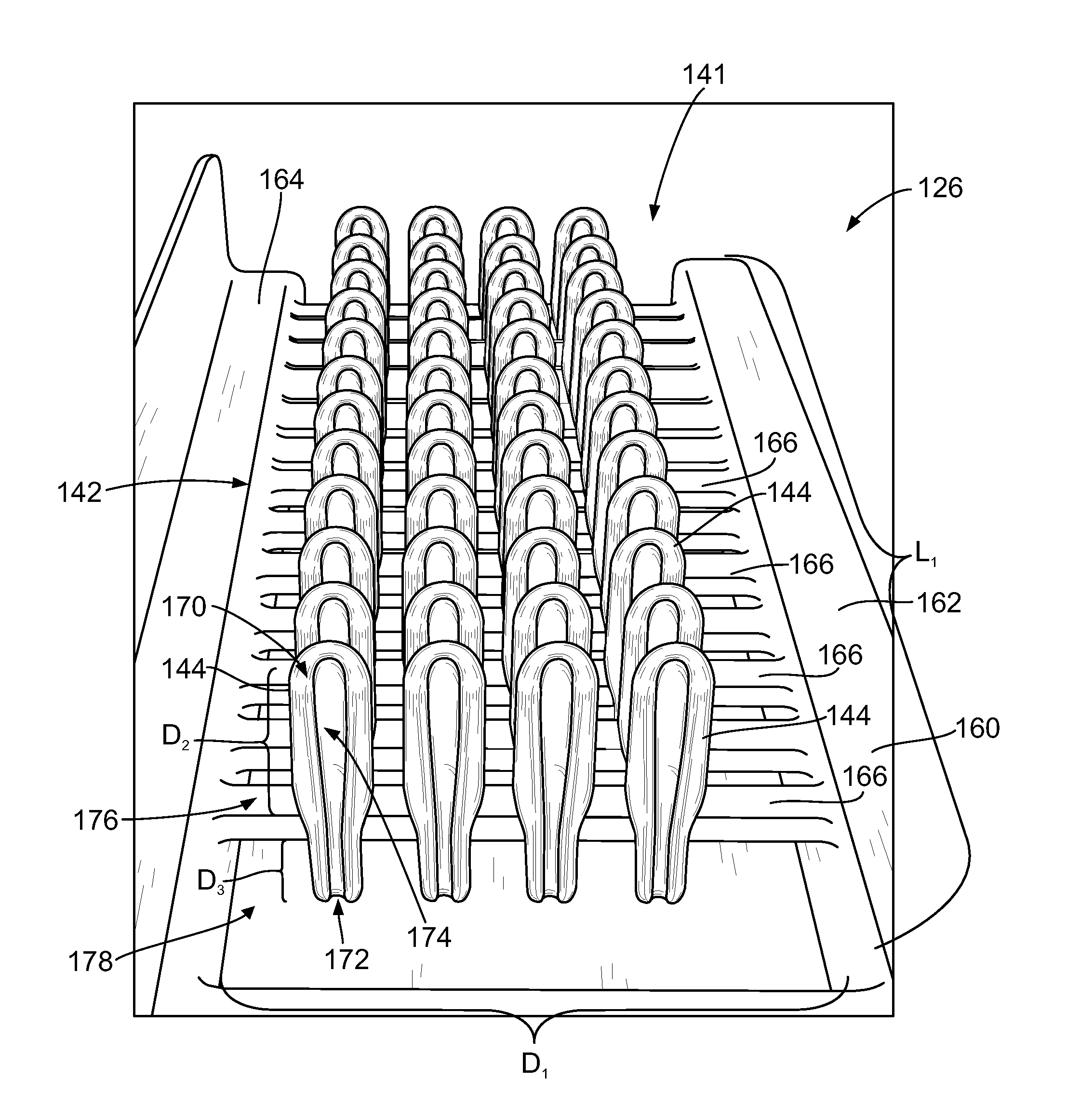
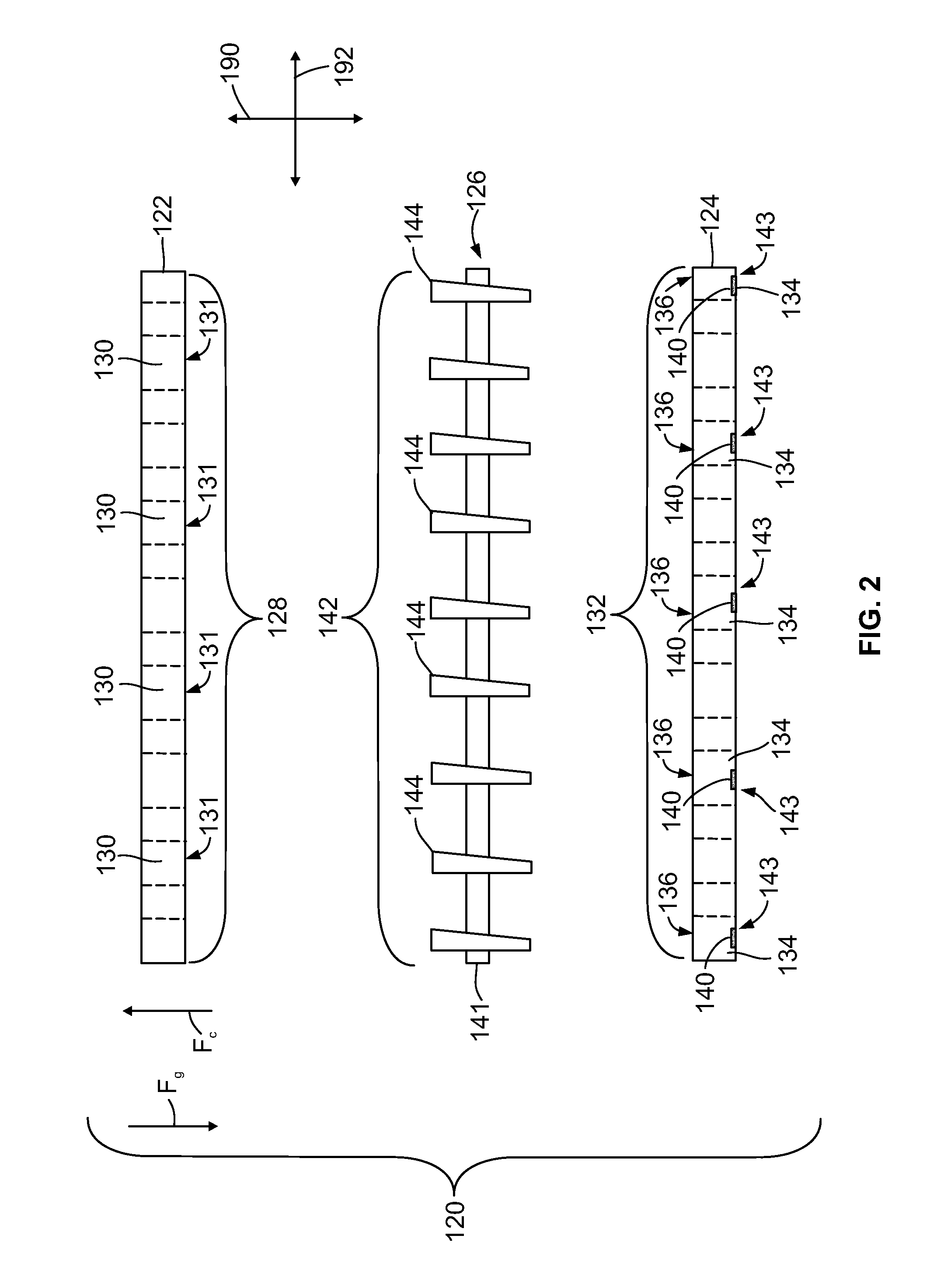
[0008]In accordance with one embodiment, a method for venting a well into which a liquid enters is provided. The method includes providing a microplate having a well that includes a cavity with an open inlet and a closed end. The cavity extends between the open inlet and the closed end. The cavity is defined by a wall surface having a cross-sectional contour that includes at least one continuous section and at least one discontinuity section. The method also includes depositing a liquid into the open inlet of the well. The liquid enters the cavity and flows toward the closed end to at least partially fill the well. The liquid flows along the continuous section of the wall surface and remains separated from the discontinuity section of the wall surface, thereby maintaining a gas exhaust path along a spacing between the liquid and the discontinuity section as the liquid flows toward the closed end to permit discharge of gas from the closed end of the well.

Problems solved by technology

However, the process for providing a solution to the sample regions may have certain limitations.
When the sample region is subsequently scanned, those portions of the sample region where the bubbles prevented the interaction between the biomolecules and probes may not indicate the correct binding affinity.
However, using a separate channel to remove the bubbles adds complexity to the system and may also reduce the available space on the microarray.
Another limitation is that conventional loading stations typically use automated or robotic devices for delivering the target solution onto the sample regions.
However, the conventional loading stations are complex systems that may be very expensive and require maintenance that is also costly.
Furthermore, the loading stations may be limited in the types of microarrays (e.g., size and density of sample regions) that are compatible with the loading stations.

Method used


Image

  • Methods and systems for controlling liquids in multiplex assays
  • Methods and systems for controlling liquids in multiplex assays
  • Methods and systems for controlling liquids in multiplex assays

Examples


Embodiment Construction

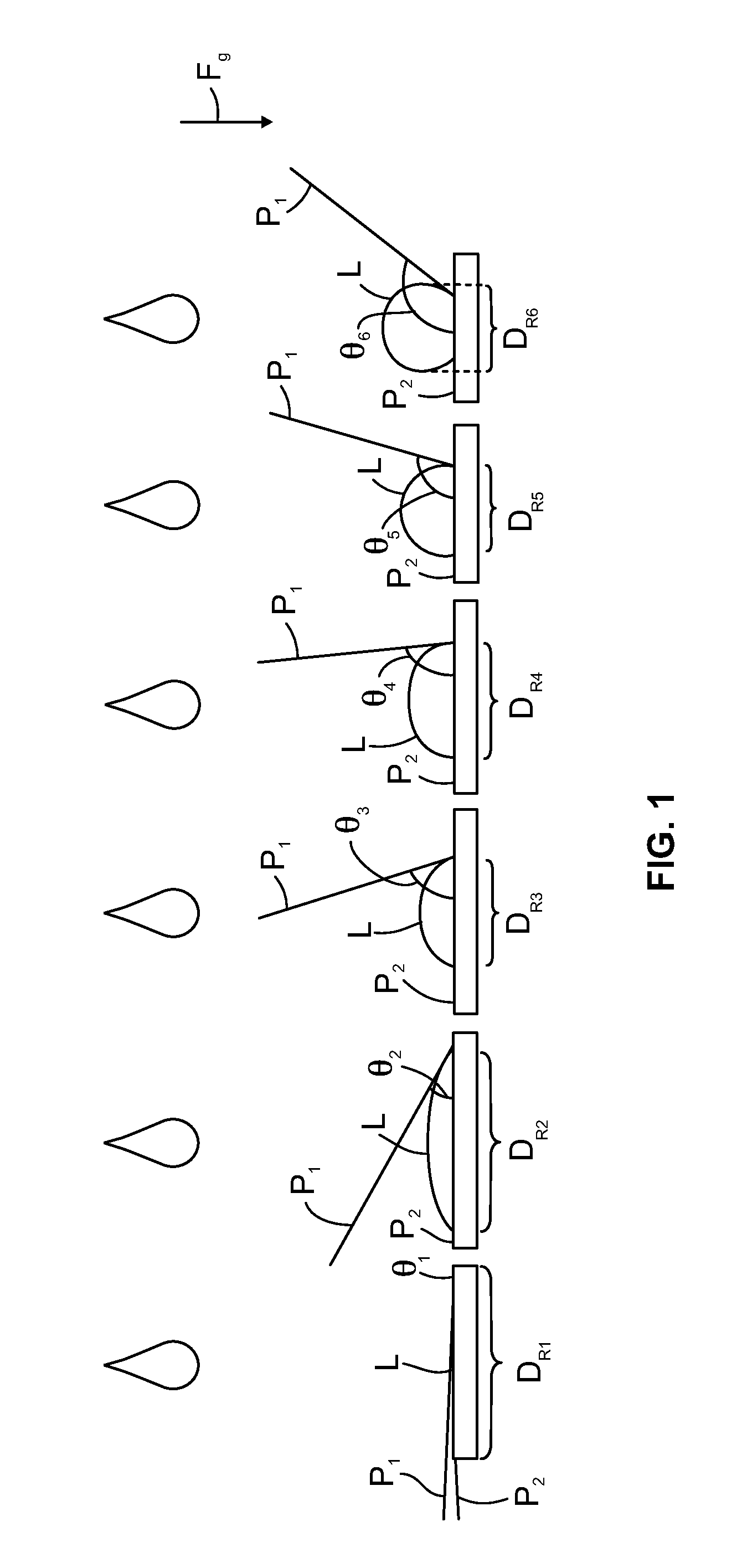
[0027]Embodiments described herein include various methods, devices, and systems that use forces experienced by a liquid within a fluidic system to control flow of the liquid and / or to vent or discharge gases from a chamber into which the liquid enters. For example, in order to control the flow of the liquid and to deposit the liquid on a desired location, various embodiments may use gravitational force, cohesive forces, and / or adhesive forces to control the flow of liquid from a source or reservoir to a sample region. Various embodiments may also use gravitational force, cohesive forces, capillary forces, surface tension and / or adhesive forces to contain a liquid within a confined space and vent gases from the confined space.

[0028]In some embodiments, the flow and / or venting of the space where the liquid is located is facilitated by or is solely accomplished by passive methods. As used herein, controlling the flow of liquid or the venting of gases “passively” means utilizing energy...


PUM

PropertyMeasurementUnit
contact angleaaaaaaaaaa
temperatureaaaaaaaaaa

Abstract

Methods and systems for venting a well that receives a liquid. The method includes providing a microplate including a well that has a cavity with an open inlet and a closed end. The cavity extends between the open inlet and the closed end. The cavity is defined by a wall surface having a cross-sectional contour that includes at least one continuous section and at least one discontinuity section. The method also includes depositing a liquid into the open inlet of the well. The liquid enters the cavity and flows toward the closed end to at least partially fill the well. The liquid flows along the continuous section of the wall surface and remains separated from the discontinuity section of the wall surface, thereby maintaining a gas exhaust path along a spacing between the liquid and the discontinuity section as the liquid flows toward the closed end.

Description

CROSS-REFERENCE TO RELATED APPLICATIONS[0001]This application claims the benefit of U.S. Provisional Application No. 61 / 160,174, filed on Mar. 13, 2009, which is incorporated by reference in the entirety.BACKGROUND OF THE INVENTION[0002]Embodiments of the present invention relate generally to methods and systems for biological and chemical analysis, and more specifically to fluidic methods and systems for preparing and using microarrays in biological and chemical analysis.[0003]Microarrays may be used in various types of biological and chemical analysis, such as in genomic research, drug screening, or screening for infectious diseases. Microarrays generally include sample regions of known biomolecules, also referred to as probes, that are immobilized onto a surface of a substrate, such as a slide. The probes may be, for example, polynucleotides, proteins, other chemical compounds, or tissues. The sample regions are arranged on the surface (e.g., rows and columns) so that each sample...

Claims


Application Information

Patent Timeline
Patent Type & Authority Applications(United States)
IPC IPC(8): C40B30/04C40B60/00C40B40/00
CPCG01N35/028Y10T436/2575G01N1/20
Inventor DEROSIER, CHAD F.
Owner ILLUMINA INC
Learn More